Structure of light tube

Inactive Publication Date: 2012-04-05
LIGITEK ELECTRONICS
View PDF12 Cites 35 Cited by
  • Summary
  • Abstract
  • Description
  • Claims
  • Application Information

AI Technical Summary

Benefits of technology

[0005]An objective of the present invention is to provide a structure of light tube, which comprises modularized arrangements of light emission element and power supply so that users are allowed to conduct maintenance and repairing operation by themselves with simple tools.
[0006]Another objective of the present invention is to provide a structure of light tube, in which light emission element and power supply are arranged at different locations, whereby heat from the light emission element is directly drained through the main body, while the power supply dissipates heat through natural air flows without relying on the main body, so that these parts do not cause thermal interference with each other and the performance of heat dissipation is improved to thereby extend the lifespan of the light tube.
[0007]To realize the above objectives, the present invention provides a structure of light tube, which comprises a main body, a power supply module, and at least one light emission element. The main body comprises a first heat dissipation zone, a second heat dissi

Problems solved by technology

This causes a severe problem that the heat dissipater is not efficient enough to drain the heat from both parts, eventually leading to damage to either one of the light source or the power supply.
Any

Method used


Image

  • Structure of light tube
  • Structure of light tube
  • Structure of light tube

Examples


Embodiment Construction

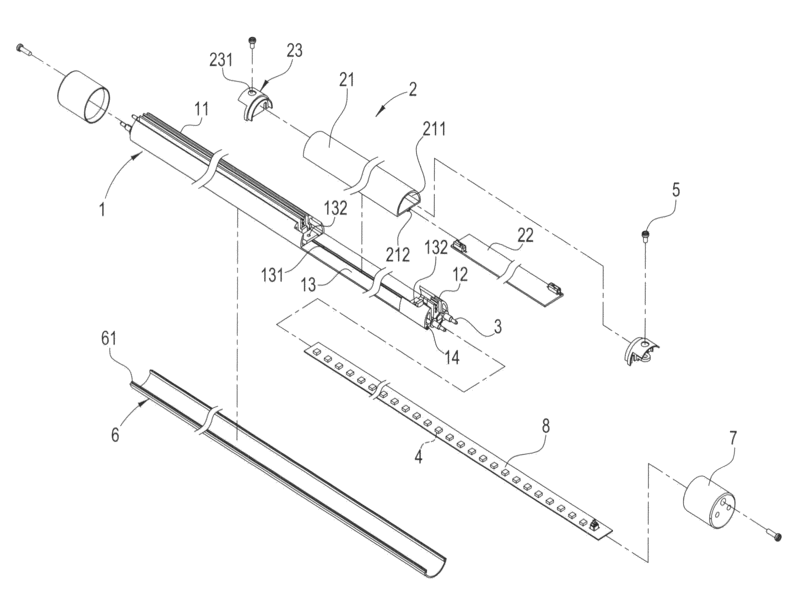
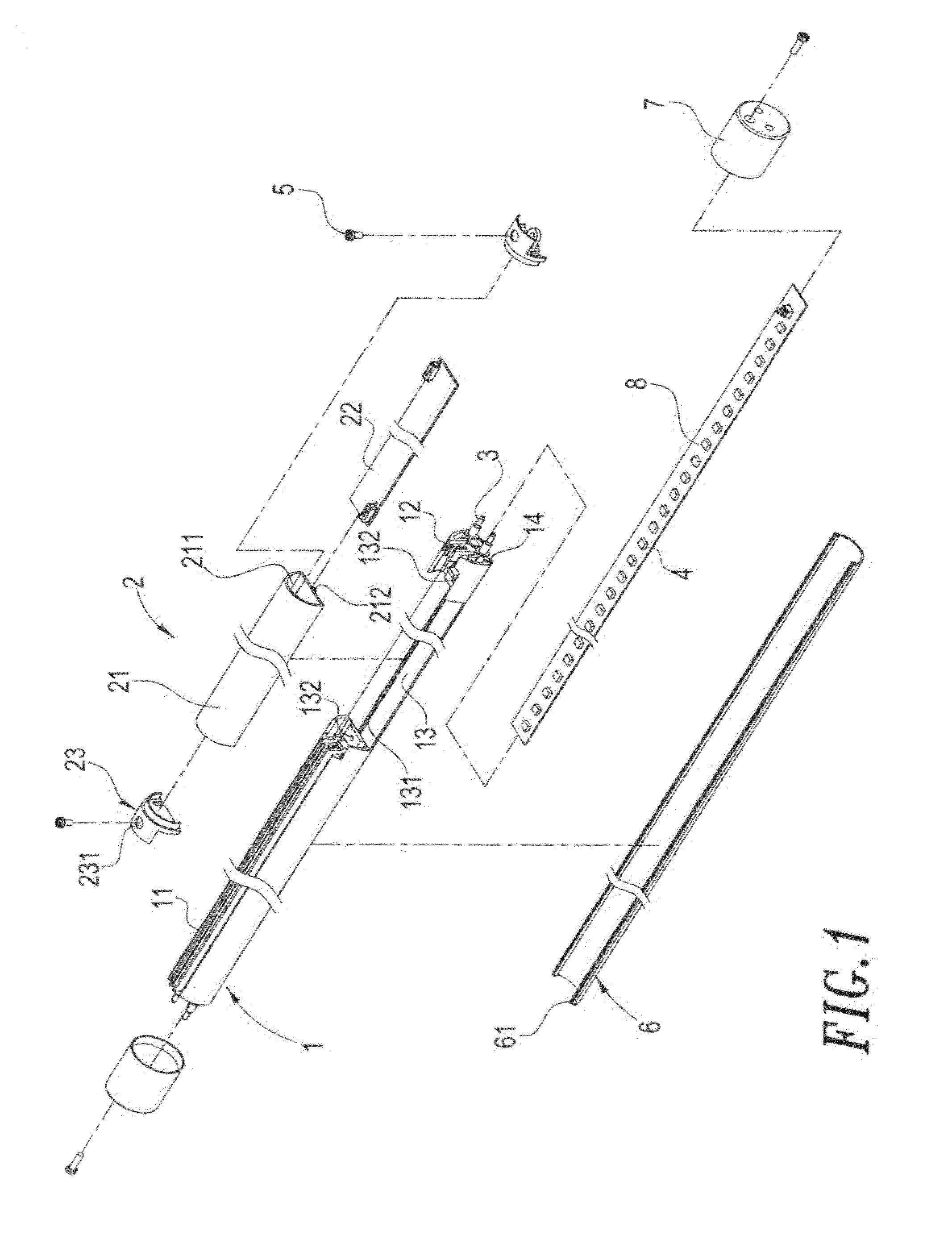
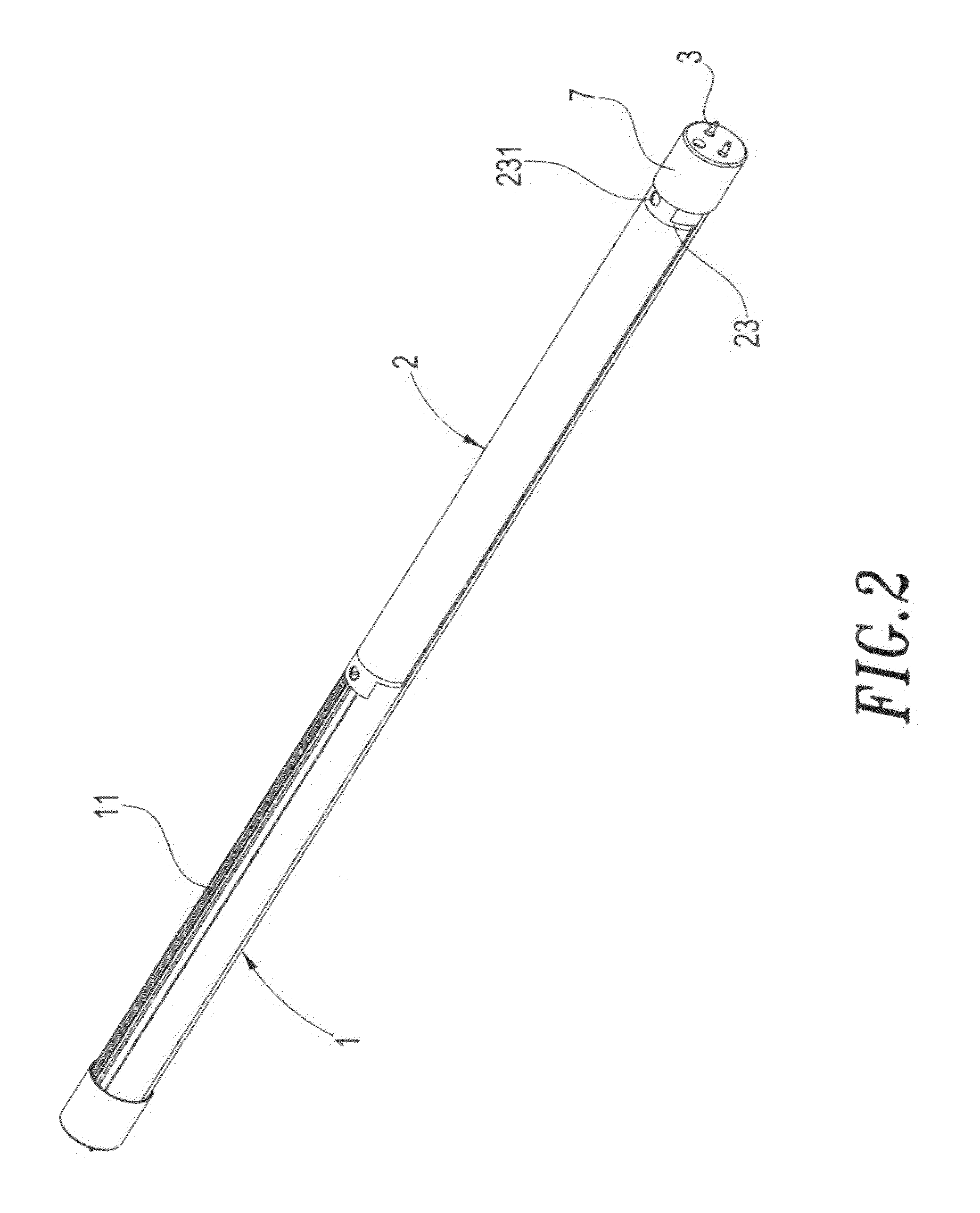
[0013]With reference to FIGS. 1-4, a structure of light tube according to the present invention comprises a main body, a power supply module, and at least one light emission element.

[0014]The main body 1 comprises a first heat dissipation zone 11, a second heat dissipation zone 12, and an accommodation chamber 13, which is located between the first heat dissipation zone 11 and the second heat dissipation zone 12. The accommodation chamber 13 receives and retains therein a power supply module 2, which comprises an enclosure 21 and a power supply device 22. The enclosure 21 forms a receiving space 211, in which the power supply device 22 is received and retained. The main body 1 has two ends that are respectively and electrically connected to two conductive terminals 3. The main body 1 is coupled to at least one light emission element 4. (In a practical example, a substrate 8 is additionally provided for coupling with and supporting the light emission element 4.)

[0015]The first heat d...


PUM


Abstract

A structure of light tube includes a main body, a power supply module, and at least one light emission element. The main body has first and second heat dissipation zones and an accommodation chamber. The main body has two ends respectively and electrically connected to two conductive terminals. The power supply module is received and retained in the accommodation chamber of the main body. The power supply module includes an enclosure forming a receiving space in which a power supply device is received and retained. The light emission element is coupled to the main body so that heat from the light emission element is directly drained through the main body, while the power supply dissipates heat through natural air flows without relying on the main body, so that there parts do not cause thermal interference with each other and the performance of heat dissipation is improved to thereby extend the lifespan of the light tube. Further, the light emission element and the power supply are of modularized arrangements, which allow the users to conduct maintenance and repairing operation with simple tools by themselves.

Description

FIELD OF THE INVENTION[0001]The present invention relates to a structure of light tube, and in particular to a structure of light tube that allows for easy replacement of power supply module.BACKGROUND OF THE INVENTION[0002]Light-emitting diode contained products are prevailing. Almost every industry provides designs that use light-emitting diode(s), among which lighting devices are most commonly operated with light-emitting diodes. The development of light-emitting diode based light tube is now getting mature. However, further improvement may be needed for heat dissipation. The state-of-the-art designs often arrange a light source and a power supply to be both fixed to a heat dissipater. When put into operation, both the light source and the light supply generate heat, which must be drained through the heat dissipater. This causes a severe problem that the heat dissipater is not efficient enough to drain the heat from both parts, eventually leading to damage to either one of the li...

Claims


Application Information

Patent Timeline
IPC IPC(8): F21V29/00
CPCF21K9/17F21V17/104F21V23/007F21V29/74F21Y2103/003F21V23/023F21V29/15F21Y2101/02F21Y2103/10F21Y2115/10F21K9/278
Inventor TUNG, I-HSINPERNG, CHIY-FERNGHSIEH, CHIA-HAOCHIEN, CHE-MINCHANG, CHE-WEI
Owner LIGITEK ELECTRONICS
Why Eureka
Try Eureka