
Method and system for generating cipher key during switching

Inactive Publication Date: 2012-04-05
ZTE CORP
View PDF3 Cites 17 Cited by
  • Summary
  • Abstract
  • Description
  • Claims
  • Application Information

AI Technical Summary

Benefits of technology

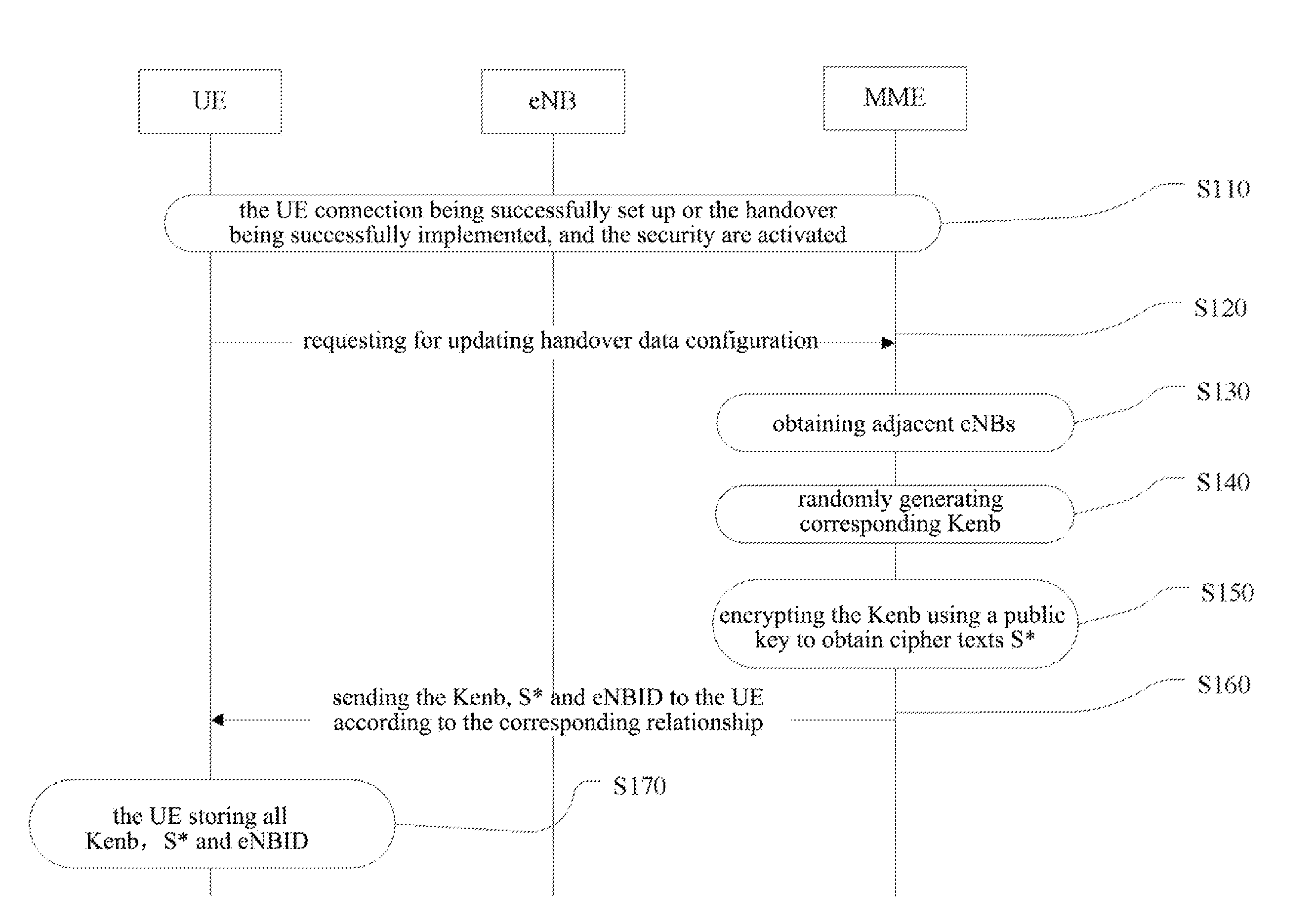
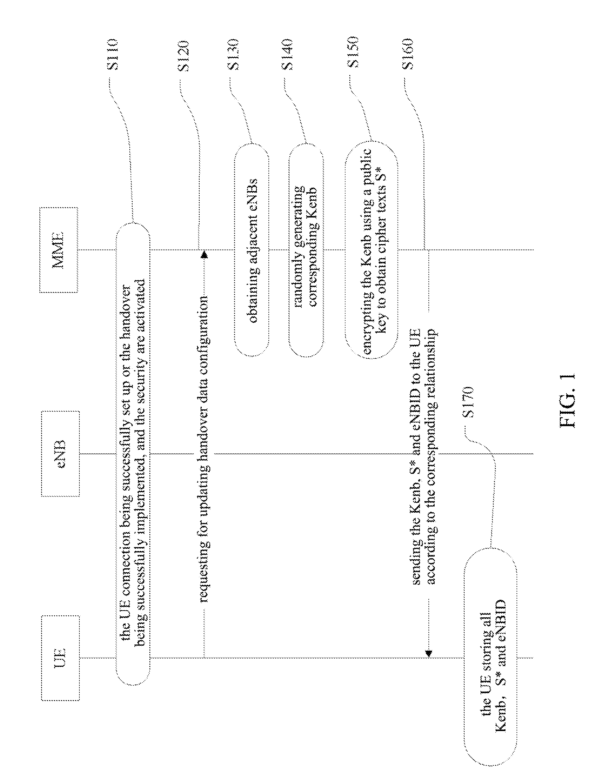
[0061]The present invention solves the problem in the existing method that the source eNB can know the Kenb of the next hop UE, and the key generating method in the handover process is simplified by completing handover data preparation when the UE is in a non-handover state, and the MME does not need to participate in the handover process, thus improving the radio performance during the handover process.

Problems solved by technology

The disadvantage of the scheme is that the source eNB can obtain the key Kenb in the next hop of the UE through deduction, thus causing potential safety hazard, meanwhile the whole calculation process is complicated, and many parameters need to be synchronized.

Method used


Image

  • Method and system for generating cipher key during switching
  • Method and system for generating cipher key during switching
  • Method and system for generating cipher key during switching

Examples


application example

[0103 One:

[0104]FIG. 3 shows the flow chart of the method for generating a key in the UE handover process according to application example one of the present invention.

[0105]The three dashed lines L1, L2, L3 divide the whole flow into three stages.

[0106]Above L1, it is MME configuration stage which is after practical networking, the adjacency relationship table of the eNB is generated according to the coverage situation of the eNB, which belongs to static data configuration.

[0107]Between L1 and L2, it is the stage in which the MME configures handover data for the UE after the UE sets up the connection.

[0108]Between L2 and L3, it is the stage in which the key Kenb is generated during the handover process of the UE.

[0109]The implementation steps will be described below:

[0110]S305: in this step, after the practical networking, all relationships between the eNB and the adjacent eNBs are configured according to the coverage situation of all eNBs. The adjacent eNB meets the following cond...

application example three

[0133]

[0134]In application example one, the reporting time of the S* is in the handover completion message, but it can also be modified such that the S* is carried in the measurement reporting message. FIG. 4 describes message change between L2 and L3 when S* is reported using a measurement message. The specific implementing steps are as follows:

[0135]S410: when the UE reports the measurement report, the report carries all S* and eNBID to the source eNB. Since the measurement report is a relative frequent message, and not every message can carry S*, the UE needs to set certain conditions, and when the conditions are met, the measurement report reported by the UE carries S*. Or, the source eNB can initiatively request the UE to carry S* when reporting the measurement report.

[0136]S415: the source eNB making a handover decision according the measurement information of the UE, and determining the target cell.

[0137]S420: after determining the target cell, the source eNB obtaining the co...


PUM


Abstract

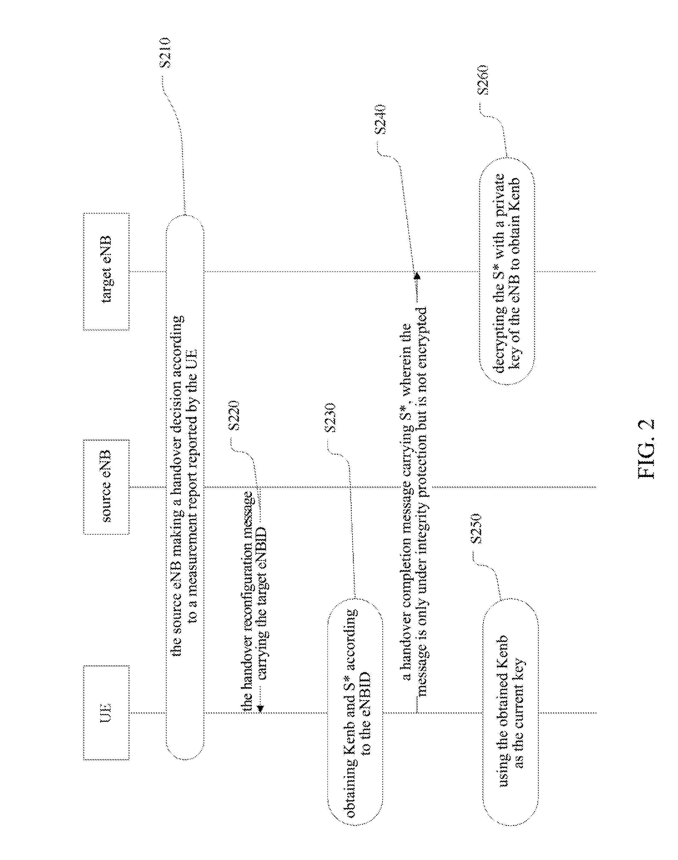
A method and a system for generating a key in a handover process, wherein the method comprises the following steps of: according to an evolved Node-B (eNB) (102) of a User Equipment (UE) (101), i.e. a source eNB, a mobility management entity (MME) (103) learning all adjacent eNBs of the source eNB (S130), and generating keys for the source eNB and each of the adjacent eNBs respectively (S140), encrypting the keys with a corresponding eNB public key respectively to obtain cipher texts (S150), and sending all cipher texts, keys and eNB identifiers to the UE (S160); in a handover process of the UE, a target eNB obtaining a cipher text corresponding to the target eNB from the UE and decrypting the cipher text with its own private key to obtain the key (S260).

Description

TECHNICAL FIELD[0001]The present invention relates to the communication field, and in particular, to a method and a system for generating a key in a handover process.BACKGROUND ART[0002]A 3GPP Evolved Packet System (EPS) is composed of an Evolved UMTS Terrestrial Radio Access Network (EUTRAN) and an Evolved Packet Core (EPC).[0003]Wherein, an EPC includes a MME (mobility management entity), which is responsible for control plane-related works such as mobility management, processing of non-access layer signaling, and user security mode management. Wherein, the MME stores Key Access Security Management Entity (KASME) of the EUTRAN, and uses the KASME and an uplink NAS SQN (non-access layer sequence number) to generate a Key eNB (KeNB) of the access layer to be used by the eNB.[0004]Wherein, in the evolved UTRAN, the base station is an evolved Node-B (eNB), which is mainly responsible for wireless communication, wireless communication management and mobility context management.[0005]Wh...

Claims


Application Information

Patent Timeline
IPC IPC(8): H04W12/06H04W36/00H04W12/04H04W12/041
CPCH04L9/0825H04W12/04H04L2209/80H04L63/06H04L63/062H04W36/0038H04W36/0061H04L63/1441H04W12/041
Inventor BAI, XIAOCHUNZHANG, XUWU
Owner ZTE CORP
Learn More