Power management method and apparatus

Inactive Publication Date: 2012-04-05
SAMSUNG ELECTRONICS CO LTD
View PDF12 Cites 4 Cited by
  • Summary
  • Abstract
  • Description
  • Claims
  • Application Information

AI Technical Summary

Benefits of technology

[0008]The present general inventive concept provides a power management method and apparatus capable of reducing standby power by to control power input from a power supply unit.

Problems solved by technology

In general, a computer, such as a mobile personal computer (PC), receives power of a high voltage of about 16 to about 19 V from the power supply unit while the Micom driving voltage in the mobile PC is about 3.3V or less, and thus, unnecessary power loss occurs in the computer that is in the system-off status.

Method used


Image

  • Power management method and apparatus
  • Power management method and apparatus
  • Power management method and apparatus

Examples


Embodiment Construction

[0041]Reference will now be made in detail to the embodiments of the present general inventive concept, examples of which are illustrated in the accompanying drawings, wherein like reference numerals refer to the like elements throughout. The embodiments are described below in order to explain the present general inventive concept by referring to the figures.

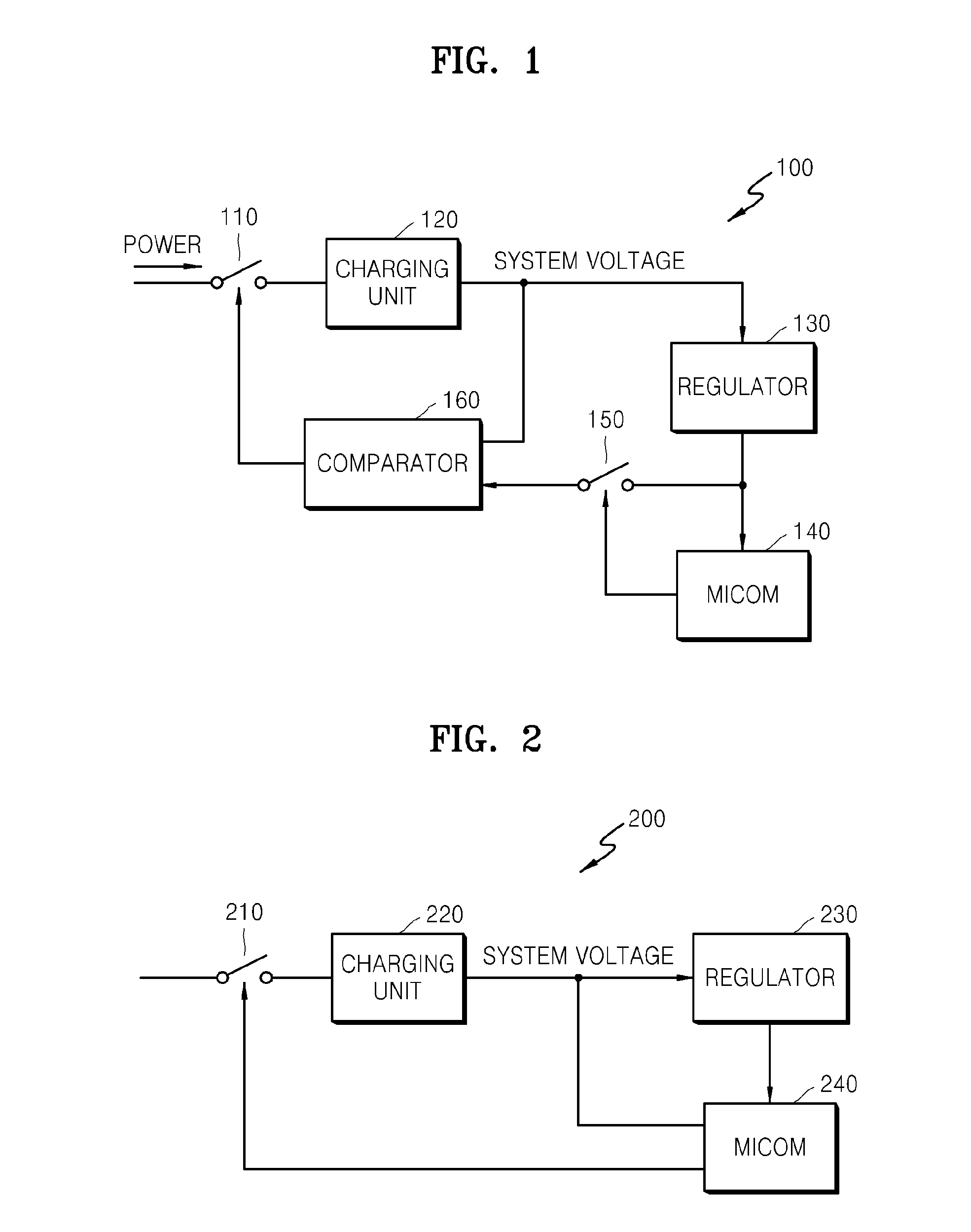
[0042]FIG. 1 is a block diagram of a user terminal 100 according to an embodiment of the present general inventive concept.

[0043]The user terminal 100 is a computer driven by an operating system, for example, a portable computer such as a laptop, an ultra mobile PC (UMPC), or a desk top computer. Alternatively, the user terminal 100 may be any device that receives power from an external source and supplies power to a plurality of devices, such as a CPU, memory, and other circuitry. For example, the user terminal 100 may further include a printing device, personal electronic device, or other image forming device.

[0044]Referring t...


PUM


Abstract

A power management method in a user terminal receives a power from a power supply unit to charge a system voltage, compares the system voltage with a preset voltage, and controls a power input from the power supply unit according to the comparison result.

Description

CROSS-REFERENCE TO RELATED APPLICATIONS [0001]This application claims the benefit of priority to Korean Patent Application No. 10-2010-0095395, filed on Sep. 30, 2010, in the Korean Intellectual Property Office, the disclosure of which is incorporated herein in its entirety by reference.BACKGROUND [0002]1. Field of the Invention[0003]The present general inventive concept relates to a power management method and apparatus, and more particularly, to a power management method and apparatus that is capable of reducing standby power by to control power supply from a power supply unit when a user terminal is in a system-off status.[0004]2. Description of the Related Art[0005]A computer generally blocks or reduces power supply to most modules in a computer system in order to reduce power consumption of the computer system when the computer does not perform operations.[0006]However, even when the computer system is in a maximum power save mode or a soft-off status, a microcomputer (Micom) n...

Claims


Application Information

Patent Timeline
IPC IPC(8): G06F1/28G06F1/32
CPCY02B60/1282G06F1/3287Y02D10/00Y02D30/50G06F1/28G06F1/30
Inventor LEE, JE-HWAN
Owner SAMSUNG ELECTRONICS CO LTD
Why Eureka
Try Eureka