Power supply device for LED and light emitting device having the same

a technology of power supply device and led light, which is applied in the direction of high-level techniques, energy consumption reduction, electroluminescent light sources, etc., can solve the problems of replacement of backup batteries and large amount of standby power, and achieve the effect of ensuring reliability of wireless controller operation and reducing power consumption

Active Publication Date: 2014-03-06
LG INNOTEK CO LTD
View PDF2 Cites 18 Cited by
  • Summary
  • Abstract
  • Description
  • Claims
  • Application Information

AI Technical Summary

Benefits of technology

[0014]As described above, according to the lighting control device based on wired/wireless communication of the present invention, the power is always obtained from the super capacitor to turn on the wireless controller, so that the turn-on state of the power generator of the wired controller is not always re

Problems solved by technology

However, if the wired control module is always maintained at the on-state for the wireless control, the great quantity of standby power is consumed.
S

Method used


Image

  • Power supply device for LED and light emitting device having the same
  • Power supply device for LED and light emitting device having the same
  • Power supply device for LED and light emitting device having the same

Examples


Embodiment Construction

[0021]Hereinafter, an exemplary embodiment of the disclosure will be described to be implemented by those skilled in the art in detail with reference to accompanying drawings. However, the disclosure can be variously modified, and not limited to the embodiment.

[0022]In the following description, when a predetermined part “includes” a predetermined component, the predetermined part does not exclude other components, but may further include other components if there is a specific opposite description.

[0023]According to a lighting control device including a wireless controller of the present invention, the lighting control device can be wirelessly controlled without always turning on a wired controller by employing an additional power unit to supply power for wireless control.

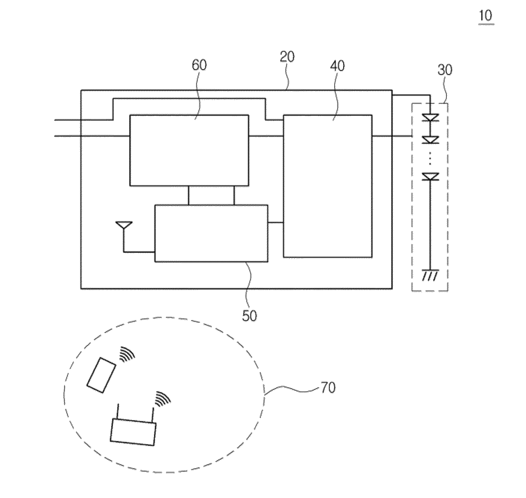
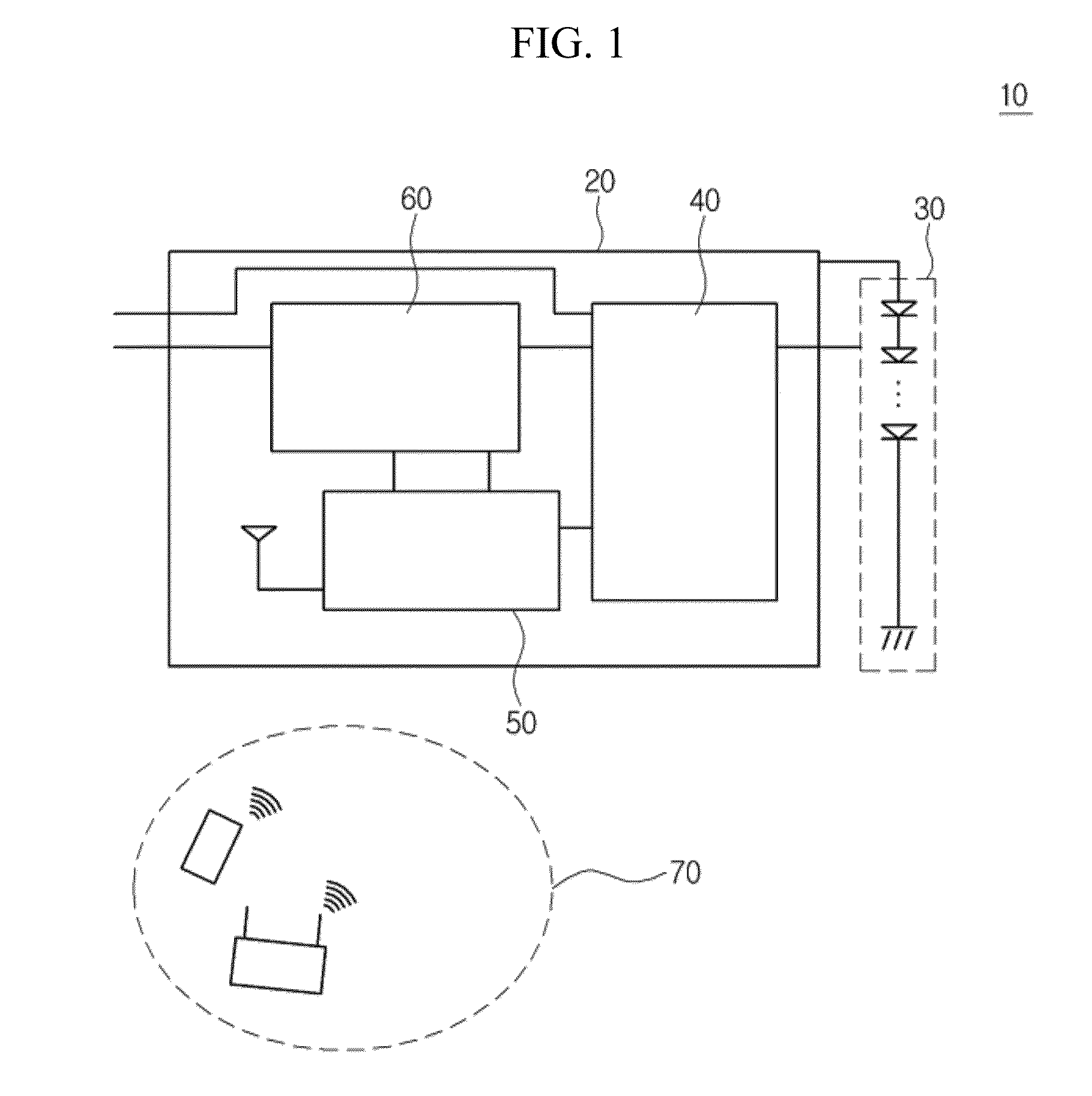
[0024]Hereinafter, a lighting apparatus 10 according to the embodiment of the disclosure will be described with reference to FIGS. 1 to 4.

[0025]FIG. 1 is a view showing the lighting apparatus 10 according to the e...


PUM


Abstract

Disclosed is a power supply device including a wired controller receiving AC power to generate a driving voltage, and outputting a lighting driving signal, a wireless controller wirelessly receiving a lighting control signal and outputting the lighting control signal to the wired controller, and a standby power supply unit receiving a reference standby voltage based on the driving voltage, storing the reference standby voltage, and supplying the reference standby voltage to the wireless controller as standby power. In the lighting control device based on wired/wireless communication, the power is always obtained from the super capacitor to turn on the wireless controller, so that the turn-on state of the power generator of the wired controller is not always required. The power consumption is reduced by reducing the standby power.

Description

CROSS-REFERENCE TO RELATED APPLICATION[0001]This application claims the benefit under 35 U.S.C. §119 of Korean Patent Application No. 10-2012-0095257, filed Aug. 29, 2012, which is hereby incorporated by reference in its entirety.BACKGROUND[0002]The disclosure relates to a power supply device for a light emitting device.[0003]A light emitting diode device (LED) is a light emitting semiconductor serving as a semiconductor PN junction device to convert electrical energy into light energy. The LED is a device to emit light through the recombination between electrons and holes at the PN junction region or the active layer by applying current to a compound semiconductor terminal.[0004]The lighting apparatus employing the LED as a lighting source is controlled through both of wired control and wireless control.[0005]In this case, when the wireless control is performed, as well as the wired control performed by receiving basic power through a cable, a wireless module is required to make wi...

Claims


Application Information

Patent Timeline
IPC IPC(8): H05B37/02H05B33/08H05B44/00
CPCH05B33/0884H05B37/0272H05B47/19H05B45/10Y02D30/70H05B47/175H05B45/52
Inventor KIM, DAE HUN
Owner LG INNOTEK CO LTD
Why Eureka
Try Eureka