Battery powered charger

a battery-powered charger and charger technology, applied in the direction of battery load switching, electrical equipment, electric vehicles, etc., can solve the problem of the possibility that the primary cell being charged therein may fail catastrophically

Active Publication Date: 2012-08-28
TOWER SEMICONDUCTOR
View PDF22 Cites 18 Cited by
  • Summary
  • Abstract
  • Description
  • Claims
  • Application Information

AI Technical Summary

Benefits of technology

[0015]According to a further preferred embodiment of the present invention, the presence of a battery in the charger provides it with an advantage over conventional chargers, in enabling easier compliance with the current policy of reducing “stand-by power” of electronic devices. If the associated battery is fully charged, the circuitry of the charger of the present invention need only be powered up when there is need to provide power to the portable electronic device. The presence of the on-board battery enables the charging circuits of the charger to be completely disconnected from the external source, such that no stand-by power at all is used from the wall socket or from the car socket. The internal battery can be used to power a very low-power detection circuit for monitoring the portable electronic device for renewed power demand. Once such a demand is detected, the charging circuits can be reconnected to the external source, and can draw power from the external source as needed. This is in contrast to conventional chargers, which generally have to be left connected in a stand-by status to the external source, drawing a trickle charge current whose need may not be immediate, but which consumes typically 250 mW for a small wall charger unit typically of the order of 5 Watts or less. Additionally, the detection circuits can also monitor the state of charge of the on-board charger battery, either by means of its terminal voltage, or by the elapsed time since the last charging operation, and can then reconnect the external source when the state of charge falls below a predetermined level, regardless of whether the electronic device has demanded current or not. This then ensures that the internal battery of the charger remains charged even when the charger is in stand-by mode.
[0021]There is further provided in accordance with yet another preferred embodiment of the present invention, a charger as described above, wherein the converter and charge control circuit further comprises circuitry to prevent supply of charging current to the at least one battery when the charger is connected to the external power source.
[0025]In such a charger, the at least one battery may be either a primary or a secondary battery. Furthermore, the control circuit may preferably be adapted to monitor the current drawn by the portable electronic device, and to reconnect the charger to the external source when such current demand exceeds a predetermined level, or to monitor the state of charge of the at least one battery, and to reconnect the charger to the external source when the state of charge falls below a predetermined level. In the latter case, the state of charge is monitored by monitoring at least one of the terminal voltage of the at least one battery, and the elapsed time since the at least one battery was charged. Finally, in such chargers, the external source may preferably be the mains supply, and disconnection of the charger from the external source essentially eliminates the stand-by current drawn from the mains supply.

Problems solved by technology

This feature is even more important in a battery powered wall charger than in a conventional battery charger, since the additional heat generated in a battery powered wall charger when operating, increases the internal temperature, and the possibility that a primary cell being charged therein may fail catastrophically

Method used


Image

  • Battery powered charger
  • Battery powered charger
  • Battery powered charger

Examples


Embodiment Construction

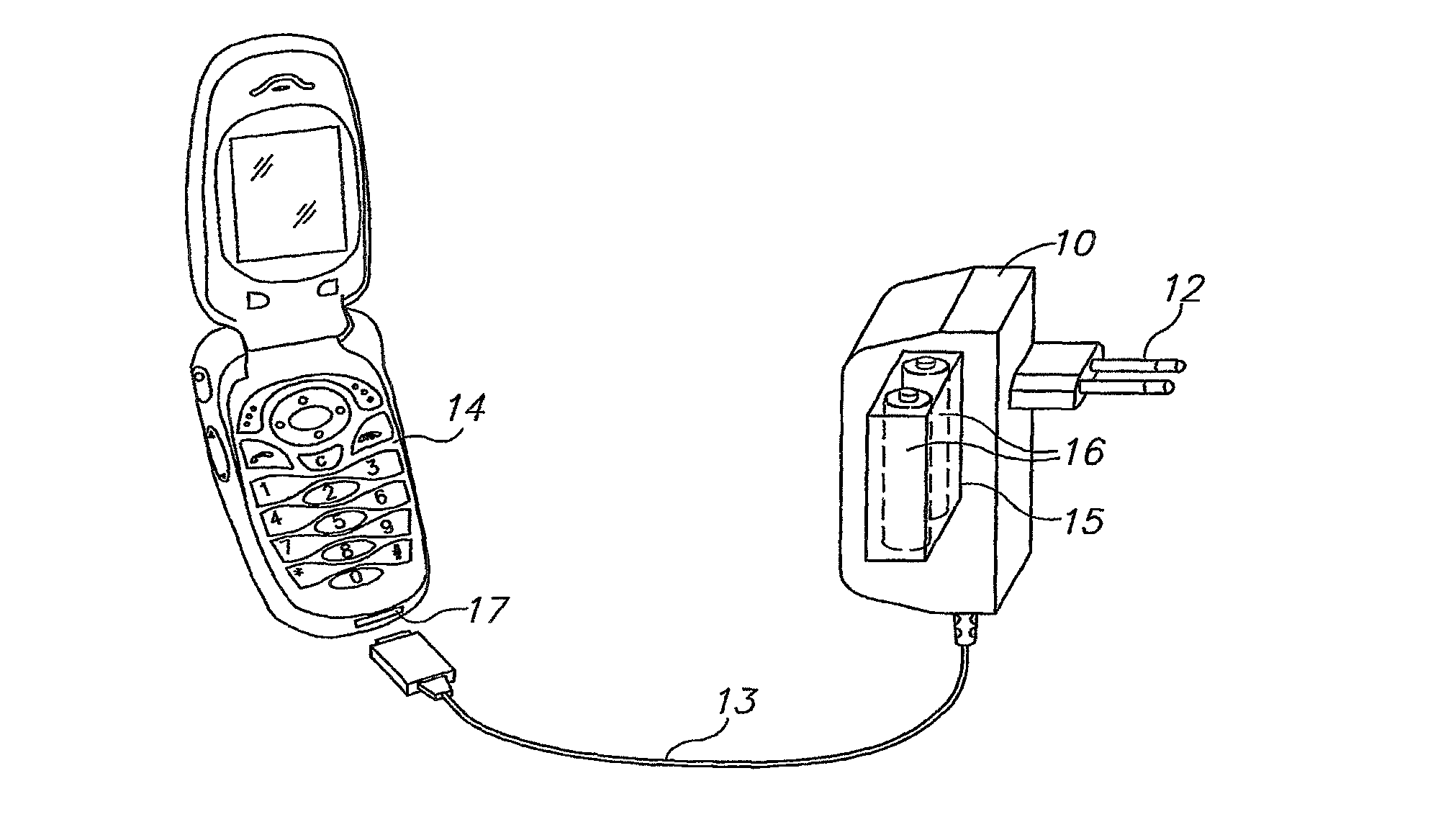
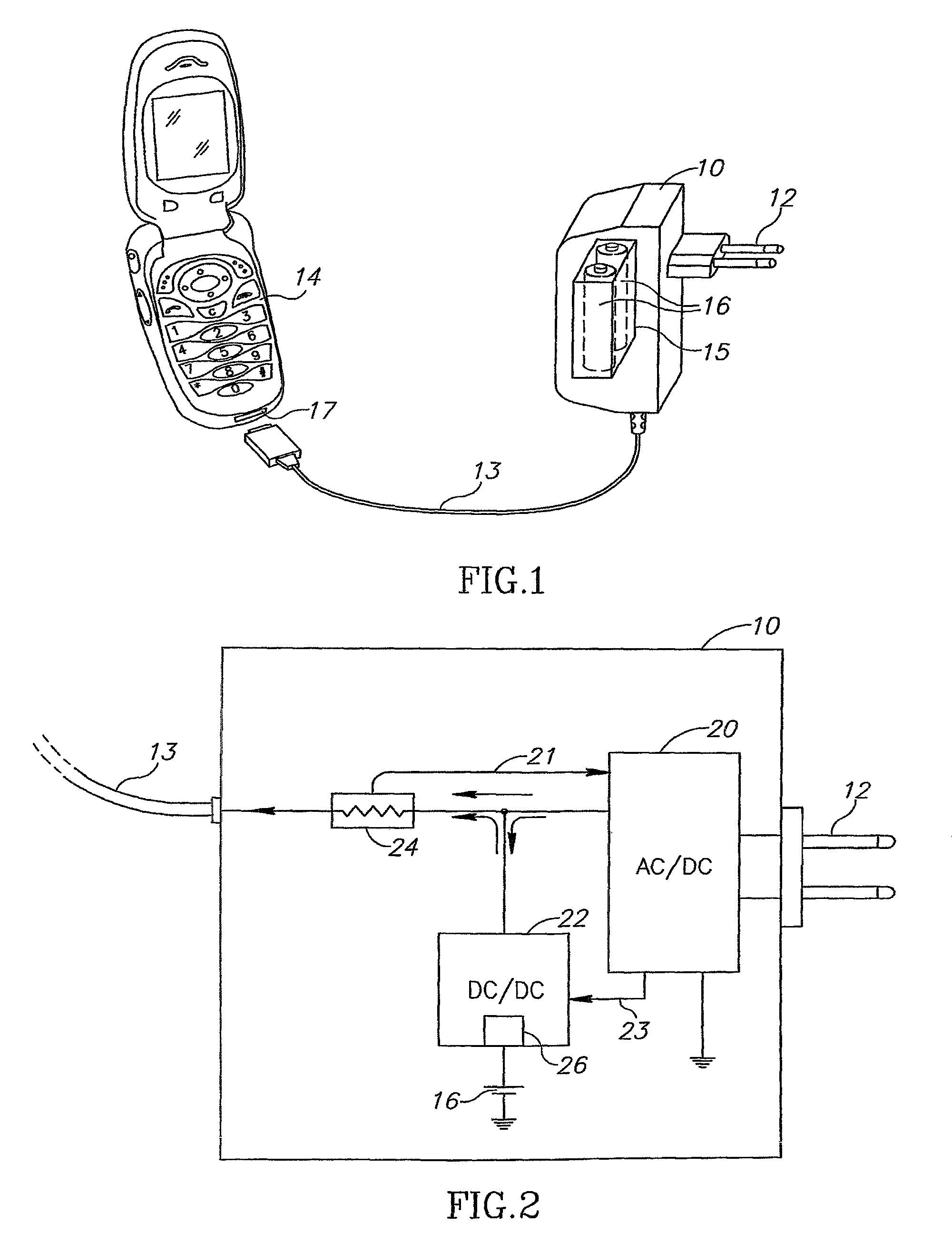
[0032]Reference is now made to FIG. 1, which illustrates schematically a wall charger 10, constructed and operative according to a first preferred embodiment of the present invention, The wall charger preferably has conventional power pins 12 for inserting into a wall socket (not shown), though it may also use a conventional plug on the end of a flying lead cable, or a push-in plug for use with a cigarette lighter socket in a car. A cable 13 provides connection to a mobile telephone 14, used as an example of a portable electronic device which can be charged by the wall charger. The output may equally well be provided in the form of a cradle in which the phone or other electronic device sits without a connection cable. The wall charger 10 differs, however, from a conventional wall charger in that it also contains a battery cavity 15, inside of which can be installed one or more cells or batteries 16, which are preferably secondary. Alternatively and preferably, primary cells or batte...


PUM


Abstract

A charger for recharging the batteries of a portable electronic device even when no external power source is available. A battery or cell is installed within the charger, and when no access is available to a fixed power source into which the charger can be plugged, the internal battery or cell can be used to recharge the electronic device. The internal battery can be a primary battery or a secondary battery. In the latter case, the internal battery can be maintained in a charged state by means of circuitry which, when the charger is plugged into the external power source, charges the internal battery as well as the battery of the electronic device. The external power source can be either an AC power wall socket, in which case the charger includes AC / DC voltage conversion circuits, or a car lighter socket, or the DC output of a conventional wall charger.

Description

RELATED APPLICATIONS[0001]This application is a National Phase Application filed under 35 USC §371 of PCT Application No. PCT / IL2007 / 001582 with an International filing date of Dec. 20, 2007, which claims priority of U.S. Provisional Application No. 60 / 996,220, filed Nov. 7, 2007 and U.S. Provisional Application No. 60 / 875,814, filed Dec. 20, 2006. Each of these applications is herein incorporated by reference in their entirety for all purposes.FIELD OF THE INVENTION[0002]The present invention relates to the field of charging devices for portable electronic equipment, especially those for use with mobile telephones.BACKGROUND OF THE INVENTION[0003]Portable electronic devices generally use internal rechargeable batteries for operation. In order to maintain the internal batteries in a state of charge, the device is generally recharged at regular intervals using a wall mains adaptor unit, whose function is to convert the comparatively high voltage AC mains voltage available at wall soc...

Claims


Application Information

Patent Timeline
Patent Type & Authority Patents(United States)
IPC IPC(8): H02J7/00
CPCH02J7/0054H02J7/0068H02J7/0042H02J7/02H02J7/342H02J5/00
Inventor MANOR, DRORSAAR, AMNONWEINSTEIN, GUYBREITING, DANIELVERCOULEN, HANS
Owner TOWER SEMICONDUCTOR
Why Eureka
Try Eureka