Castor Having a Greater Structural Strength to Bear a Heavier Load

a technology of a castors and a greater structural strength, applied in the field of castors, can solve the problems of easy noise generation of the castors during rolling, and achieve the effects of greater rotational force, greater length, and heavier load

Inactive Publication Date: 2012-04-12
TSAI PO CHUAN
View PDF16 Cites 14 Cited by
  • Summary
  • Abstract
  • Description
  • Claims
  • Application Information

AI Technical Summary

Benefits of technology

[0008]According to the primary advantage of the present invention, the shank of the upright shaft has a greater length, and the distance between the top cover and the second bushing is increased so that the bearing and the castor body can bear a heavier load.
[0009]According to another advantage of the present invention, the distance between the top cover and the second bushing is increased so that the shank of the upright shaft and the second bushing can bear a greater rotational force to prevent the upright shaft from being loosened or vibrating during a long-term utilization so as to enhance the lifetime of the castor.
[0010]According to a further advantage of the present invention, the first bushing is located between the bearing and the castor body to provide a noise suppression function during rotation of the bearing.
[0011]According to a further advantage of the present invention, the first bushing can calibrate the size of the bearing and the castor body so that the bearing and the castor body are combined closely.
[0012]According to a further advantage of the present invention, the second bushing is located between the upright shaft and the castor body to provide a noise suppression function during rotation of the castor body. Further benefits and advantages of the present invention will become apparent after a careful reading of the detailed description with appropriate reference to the accompanying drawings.
[0013]FIG. 1 is a perspective view of a castor for an office chair in accordance with the preferred embodiment of the present invention.

Problems solved by technology

Further, the parts of the castor 1 are made of metal so that the castor 1 easily produces noise during rolling.

Method used


Image

  • Castor Having a Greater Structural Strength to Bear a Heavier Load
  • Castor Having a Greater Structural Strength to Bear a Heavier Load
  • Castor Having a Greater Structural Strength to Bear a Heavier Load

Examples


Embodiment Construction

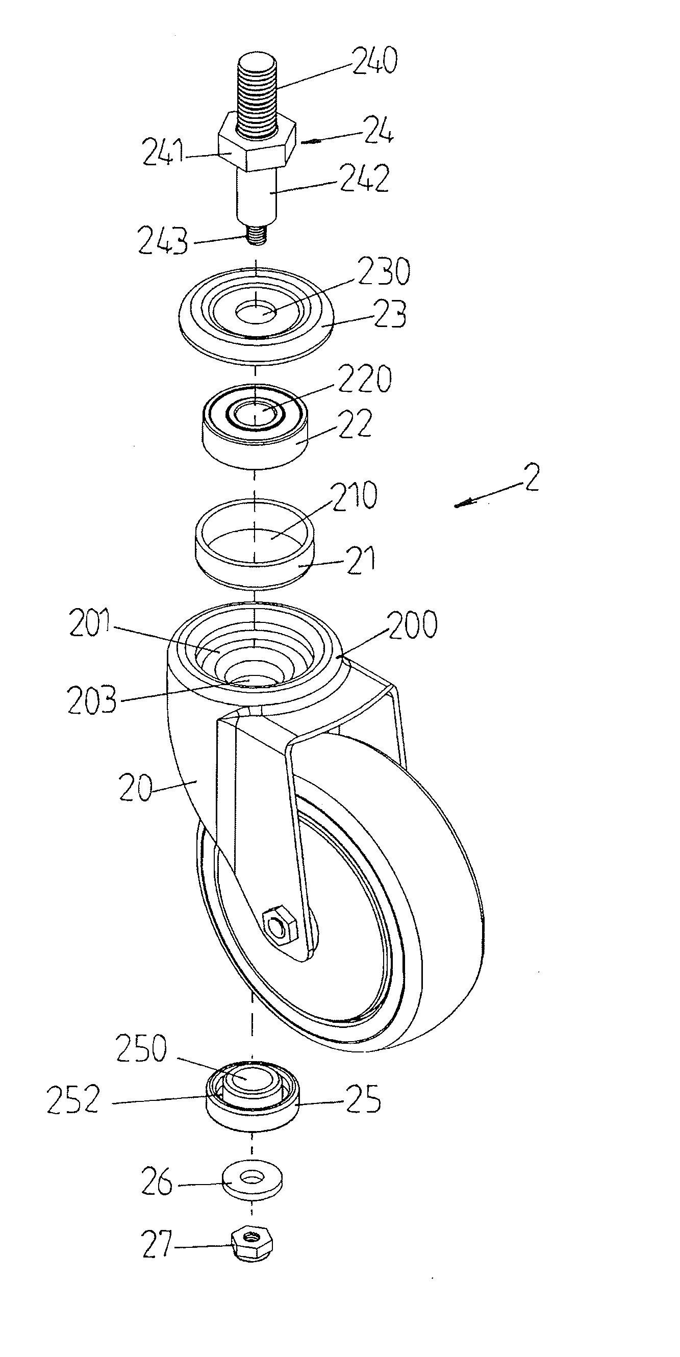
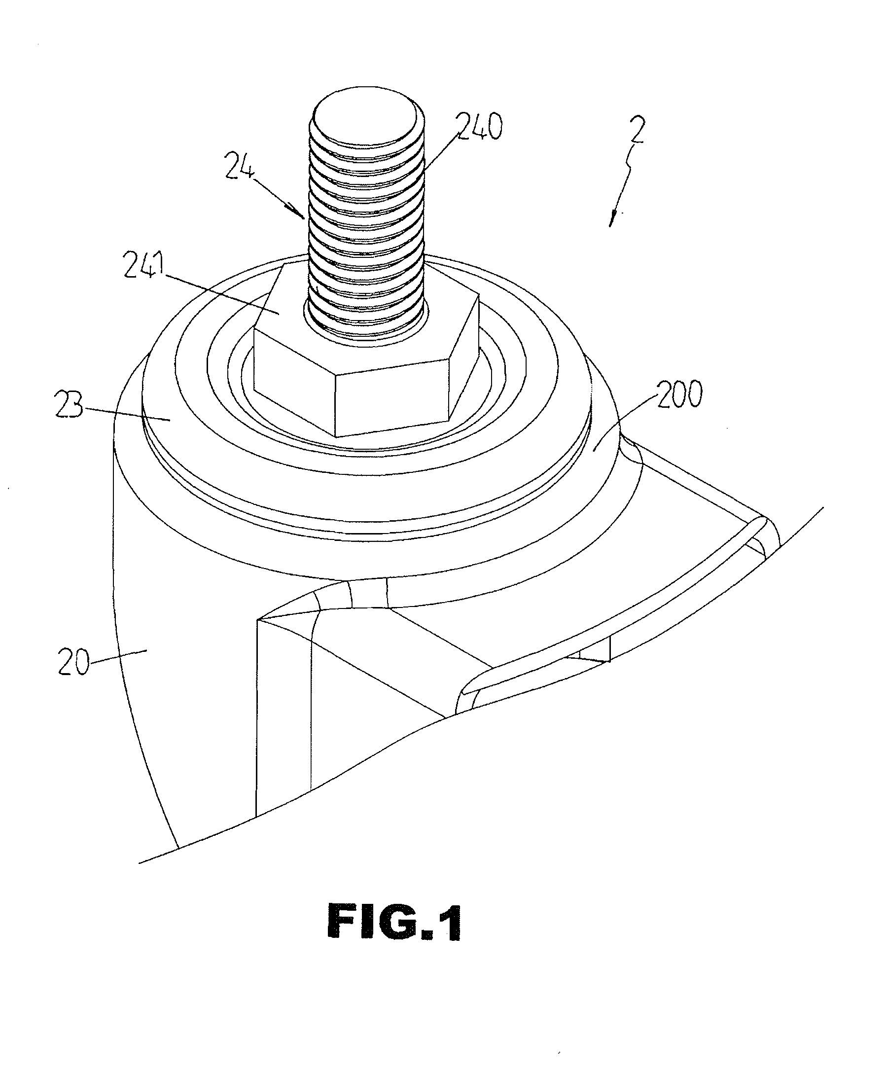
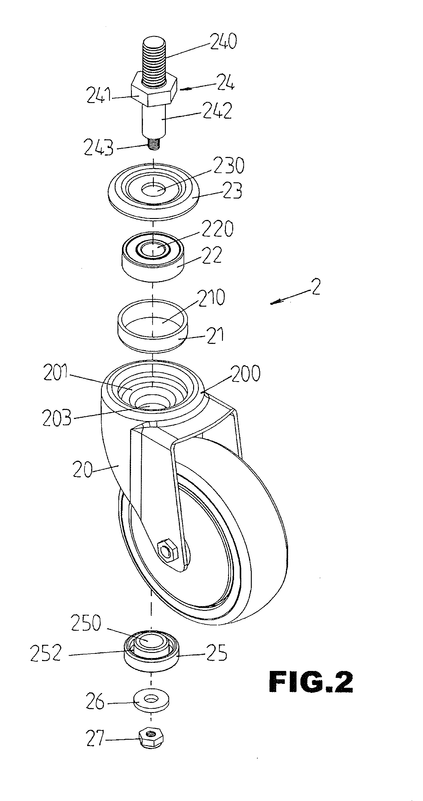
[0020]Referring to the drawings and initially to FIGS. 1-3, a castor 2 for an office chair in accordance with the preferred embodiment of the present invention comprises a castor body 20, a first bushing 21 mounted on a top 200 of the castor body 20, a bearing 22 mounted in the first bushing 21, a top cover 23 mounted on the top 200 of the castor body 20 to cover the first bushing 21 and the bearing 22, a second bushing 25 mounted on a bottom 202 of the castor body 20, and an upright shaft 24 in turn extending through the top cover 23, the bearing 22, the castor body 20 and the second bushing 25.

[0021]The castor body 20 is made of iron and has an inner portion formed with a receiving chamber 203 to allow insertion of the second bushing 25. The top 200 of the castor body 20 has a surface formed with a mounting recess 201 connected to the receiving chamber 203 for mounting the first bushing 21. The mounting recess 201 of the castor body 20 has a size greater than that of the receiving...


PUM


Abstract

A castor includes a castor body, a first bushing mounted on a top of the castor body, a bearing mounted in the first bushing, a top cover mounted on the top of the castor body to cover the first bushing and the bearing, a second bushing mounted on a bottom of the castor body, and an upright shaft in turn extending through the top cover, the bearing, the castor body and the second bushing. Thus, the distance between the top cover and the second bushing is increased so that the bearing and the castor body can bear a heavier load. In addition, the distance between the top cover and the second bushing is increased so that the upright shaft and the second bushing can bear a greater rotational force.

Description

BACKGROUND OF THE INVENTION[0001]1. Field of the Invention[0002]The present invention relates to a castor and, more particularly, to a castor for an office chair.[0003]2. Description of the Related Art[0004]A conventional castor 1 in accordance with the prior art shown in FIG. 7 comprises a shaft 11 having a lower end integrally formed with a top cover 110, a castor body 10 mounted on the lower end of the shaft 11, a bottom cover 12 mounted on the lower end of the shaft 11, a first bearing 13 mounted on the shaft 11 and biased between the top cover 110 and the castor body 10, and a second bearing 14 mounted on the shaft 11 and biased between the castor body 10 and the bottom cover 12. However, the distance between the top cover 110 and the bottom cover 12 is short so that the shaft 11 and the castor body 10 cannot bear a heavier load. In addition, the distance between the top cover 110 and the bottom cover 12 is short so that lower end of the shaft 11 cannot bear a heavier rotationa...

Claims


Application Information

Patent Timeline
Patent Type & Authority Applications(United States)
IPC IPC(8): B60B33/00
CPCB60B33/0007B60B33/0021B60B33/0039B60B33/0049B60B33/0057Y10T16/199B60B33/0073B60B2380/12B60B2380/50B60B2380/90B60B2900/711B60B33/0068
Inventor TSAI, PO-CHUAN
Owner TSAI PO CHUAN
Why Eureka
Try Eureka