
Flashing tape

a flashing tape and tape technology, applied in the field of flashing tape, can solve the problems of damage to the health of the occupants of the building, damage to the occupants' health, and deterioration of wood, and achieve the effect of sufficient sealant compatibility

Inactive Publication Date: 2012-04-12
BERRY SPECIALTY TAPES LLC
View PDF5 Cites 26 Cited by
  • Summary
  • Abstract
  • Description
  • Claims
  • Application Information

AI Technical Summary

Benefits of technology

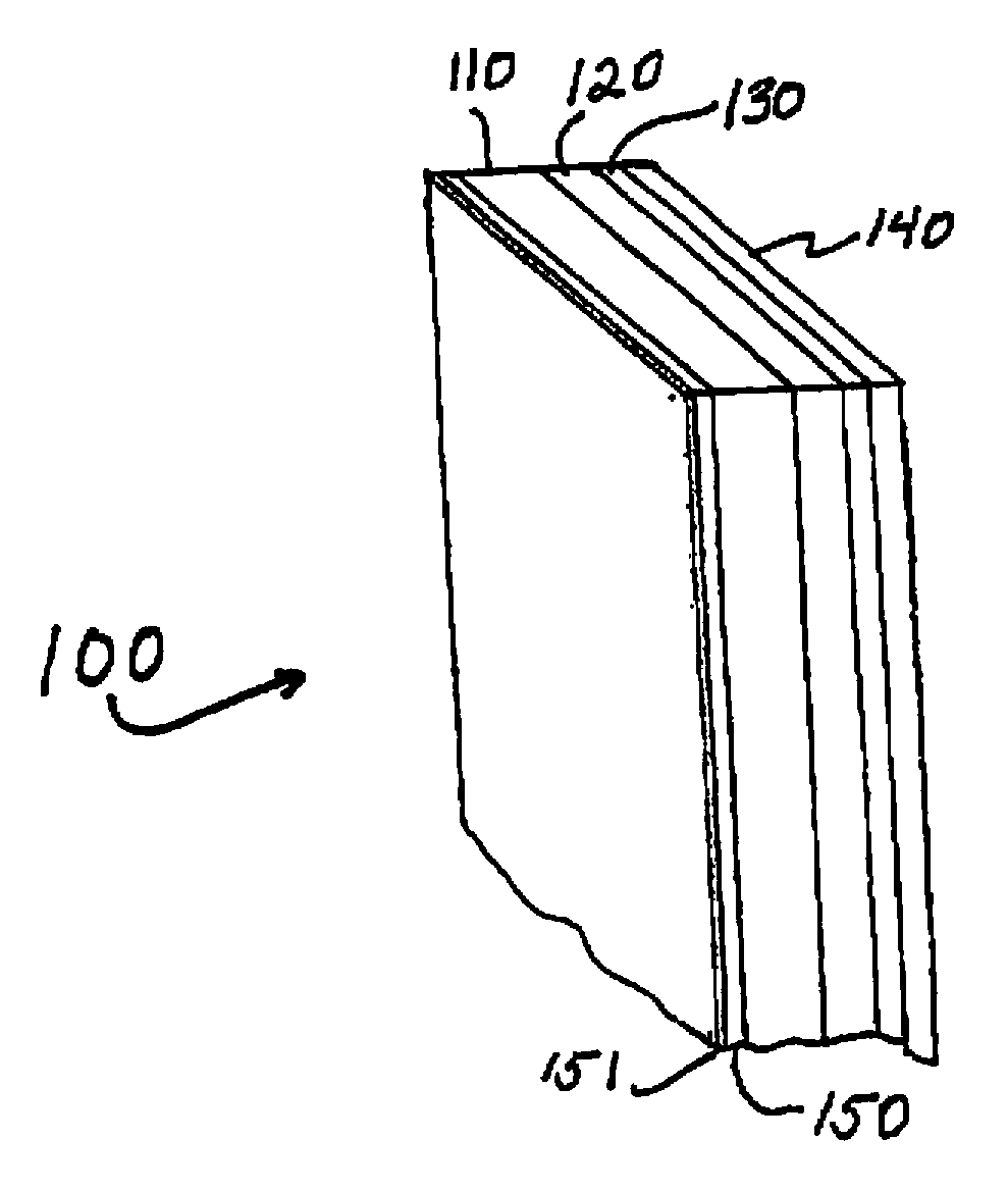
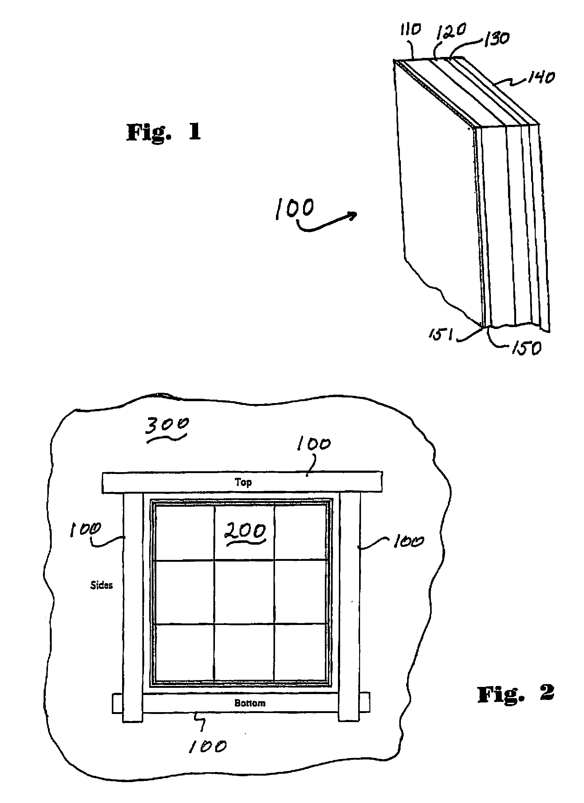
The patent describes a flashing tape that is useful for sealing openings in walls and roofs, as well as for preventing moisture infiltration. The flashing tape has three layers: a moisture-impervious layer with raised projections for drainage, a layer of cross-linked closed cell polymeric foam, and a layer of pressure-sensitive adhesive. The flashing tape system has been tested and found to meet industry-specific standards for sealant compatibility and performance. Its unique design allows for air and water flow through the surface of the tape, while also providing a strong seal to prevent moisture infiltration.

Problems solved by technology

In particular, exterior moisture such as rain, when in long term contact with the interior structure of a building, can cause rotting of wood and growth of mold.
The rotting of wood leads to structural damage and very expensive repairs.
Molds can harm the health of the occupants of the building by causing allergies and other ailments.
Today the entire residential and commercial construction marketplace is threatened by the runaway costs of litigation and claims management due to the effects of mold and water damage to parts of the building envelope affected by the use of the present state of the art in flashing systems.
The problem with conventional flashing materials and methods is that once water does enter behind trim and cladding it has no easy way to drain or escape.
The lack of a drainage plane at the critical building interface and in the flashing materials then becomes a disadvantage by trapping moisture between the flashing tape and the exterior trim, cladding and siding.
The typical chemical structure limits the range of temperature performance and installation.
They commonly experience compatibility problems with sealants used around the window and door openings used to seal gaps and seal the window in place.
These products in their use of all impermeable materials and solid face films fail to create a drainage plane for water to migrate down the edges of the window away from the door or critical building interface and fail to introduce air to aid in evaporation.
Moreover commonly used sealants often do not provide acceptable performance over a wide range of ambient temperature and moisture conditions over the life cycle of the windows, doors, etc.
Under extreme weather conditions such as very high or very low temperatures, commonly used moisture barrier materials often separate from the substrate surface to which they are attached, leaving gaps through which moisture can enter to cause damage to the underlying structure.

Method used


Image

  • Flashing tape
  • Flashing tape
  • Flashing tape

Examples


example 1

[0051]In accordance with a modified ASTM E2273-03 test method the flashing tape of the present invention was tested for drainage rate of water shed off building trim and cladding and comes into contact with the flashing tape. The flashing tape is installed over a nailing fin. A clear polyacrylic plate is disposed over the flashing tape to simulate the installation of cladding and trim boards. The rate of drain is calculated by measuring the weight of water passing between the flashing tape and polyacrylic plate over a period of time. Table 1 below sets forth the drainage rate results for samples of the flashing tape of the invention and comparison tapes (which are not in accord with the invention). Each of the tape samples was four inches in width and of the same length.

[0052]The flashing tape of the invention identified in Table 2 as Tape #1, included a 10 mil thick nonporous polyethylene face sheet coextruded with a cross linked closed cell polyethylene foam. The polyethylene face...

example 2

[0057]Pursuant to AAMA 711-07 Voluntary Specification For Self Adhering Flashing Used For Installation Of Exterior Wall Fenestration Products the flashing tape of the invention was tested for adherence to minimum performance requirements. The specific methods and associated results are set forth below in Table 3.

TABLE 3AAMA 711-07Test Method and Minimum RequirementsTest Results5.1Tensile Strength Machine Direction per ASTM15.4 lbsD 5034 at 73° F. and 50% RH Minimum Value2.9 lbs / inch5.2Water Penetration Resistance Around Nails perNo water foundASTM D 1970-01 Sec 7.9 Procedure Minimum31 mm(1.2 in) water5.3Peel Adhesion per ASTM D 3330, Method F,As Described in Sections 4.6 and 16.0 of thatMethod5.3.224 hr dwell at 73° F. / 50% RH Minimum Peel4.75 lb / linear Value 0.26 N / mm (1.5 lb / in) OSBinch5.3.224 hr dwell at 73° F. / 50% RH Minimum Peel4.3 lb / linear Value 0.26 N / mm (1.5 lb / in) Plywoodinch5.3.224 hr dwell at 73° F. / 50% RH Minimum Peel4.4 lb / linear Value 0.26 N / mm (1.5 lb / in) Anodizedinch...


PUM

PropertyMeasurementUnit
heightaaaaaaaaaa
distanceaaaaaaaaaa
thicknessaaaaaaaaaa

Abstract

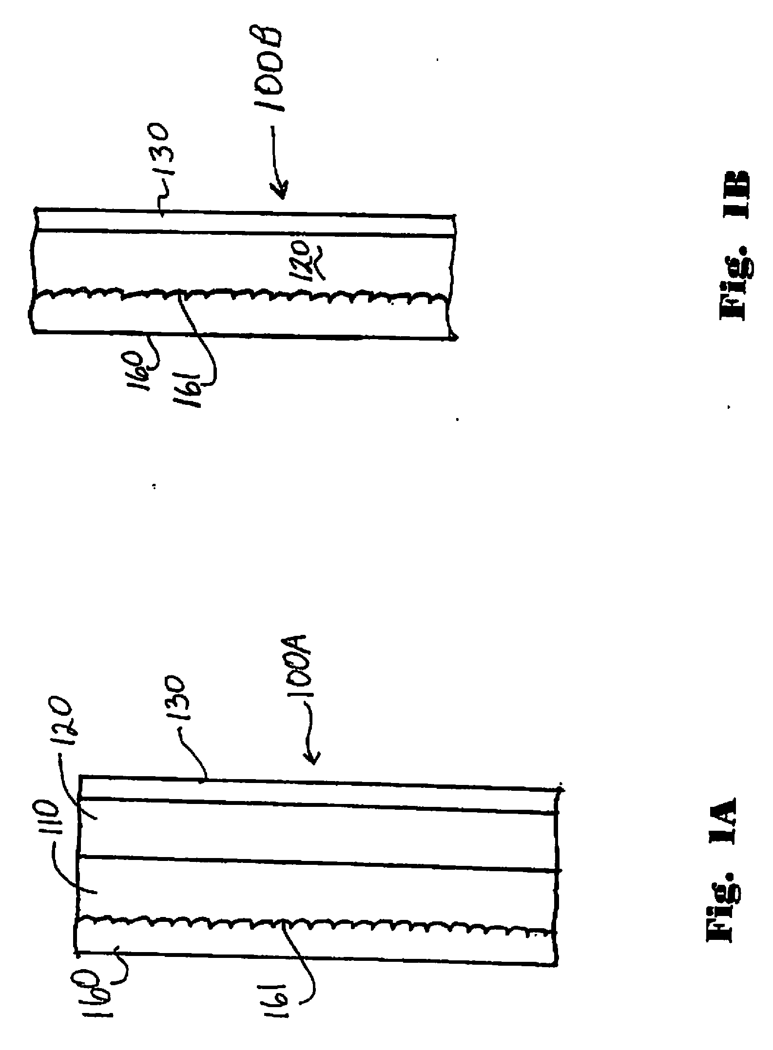
A flashing tape includes a moisture-impervious nonporous first layer having a drainage plane surface for providing drainage of moisture, the drainage plane surface being textured with embossed or otherwise raised spaced apart projections, the spaces between the projections, in conjunction with an overlay of construction material, defining a nondirectional flow path to permit the drainage of moisture and flow of air along said surface; a moisture-impervious second layer of closed cell polymeric foam which is bonded on a first side to the moisture-impervious first layer; and, a layer of pressure sensitive acrylic based adhesive applied to a second side of the moisture-impervious layer.

Description

CROSS REFERENCE TO RELATED APPLICATIONS[0001]The present application is a continuation in part of U.S. application Ser. No. 11 / 818,284 filed Jun. 14, 2007, to which priority is claimed and which is herein incorporated by reference in its entirety.BACKGROUND[0002]1. Field of the Invention[0003]The present application relates to building construction, and particularly to a material and method for providing a flashing system for protecting buildings and other structures from moisture.[0004]2. Background of the Art[0005]Prevention of water damage is an ongoing task of the building construction industry. In particular, exterior moisture such as rain, when in long term contact with the interior structure of a building, can cause rotting of wood and growth of mold. The rotting of wood leads to structural damage and very expensive repairs. Molds can harm the health of the occupants of the building by causing allergies and other ailments.[0006]Entry of moisture can occur over time by a combi...

Claims


Application Information

Patent Timeline
Patent Type & Authority Applications(United States)
IPC IPC(8): E04B1/68B32B7/10B32B7/00C09J7/29
CPCB32B3/30Y10T428/24355B32B27/065B32B2266/025B32B2266/06B32B2266/08B32B2307/7246B32B2307/726B32B2419/00C09J7/0289C09J7/0296C09J2400/243C09J2423/046C09J2433/00E06B1/62E06B2001/628Y10T428/1476B32B5/32C09J7/26C09J7/29
Inventor PUFAHL, JOSEPH
Owner BERRY SPECIALTY TAPES LLC
Learn More