Mobile robotic vacuum cleaner with a detachable electrical fan

Inactive Publication Date: 2012-04-12
EGENPOWER
View PDF0 Cites 5 Cited by
  • Summary
  • Abstract
  • Description
  • Claims
  • Application Information

AI Technical Summary

Benefits of technology

[0008]Thus, the user or worker can repair or install the roller brush driving structu

Problems solved by technology

Thus, the user or worker can repair or install the roller brush driving structure

Method used


Image

  • Mobile robotic vacuum cleaner with a detachable electrical fan
  • Mobile robotic vacuum cleaner with a detachable electrical fan
  • Mobile robotic vacuum cleaner with a detachable electrical fan

Examples


Example

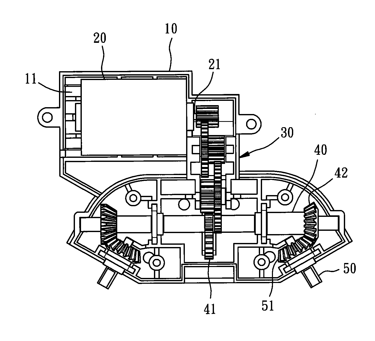
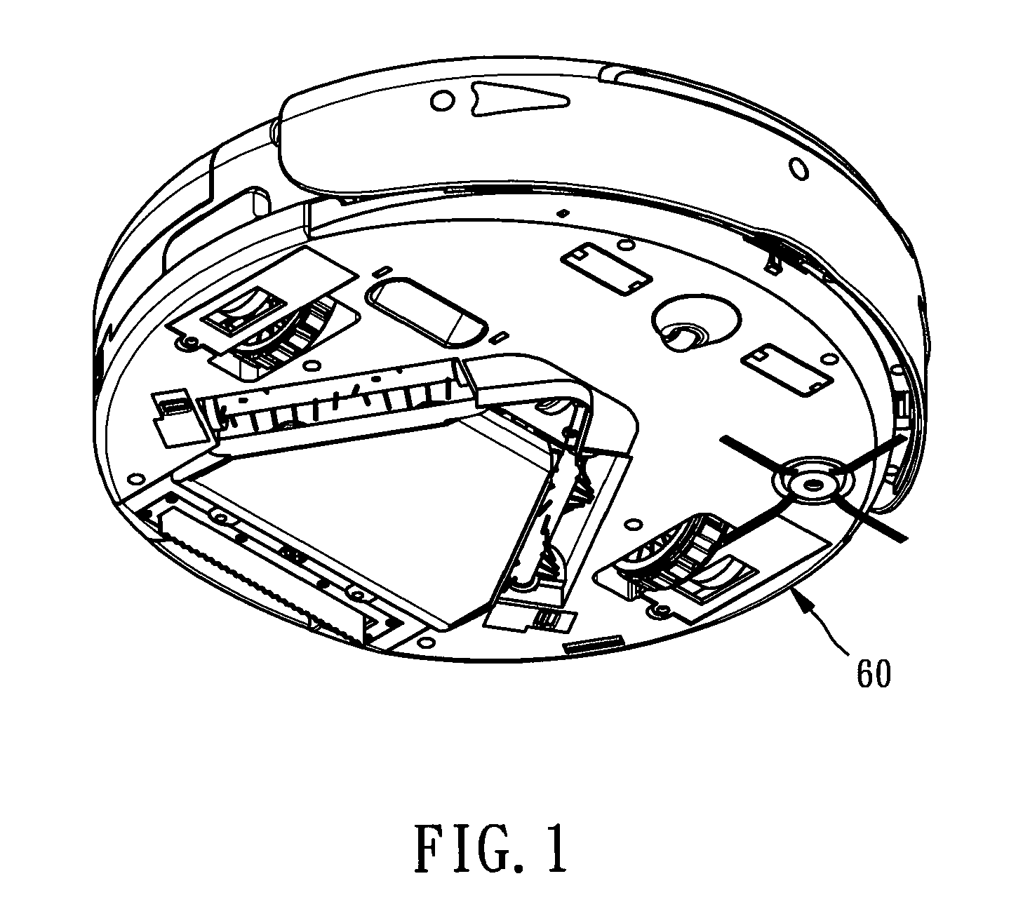
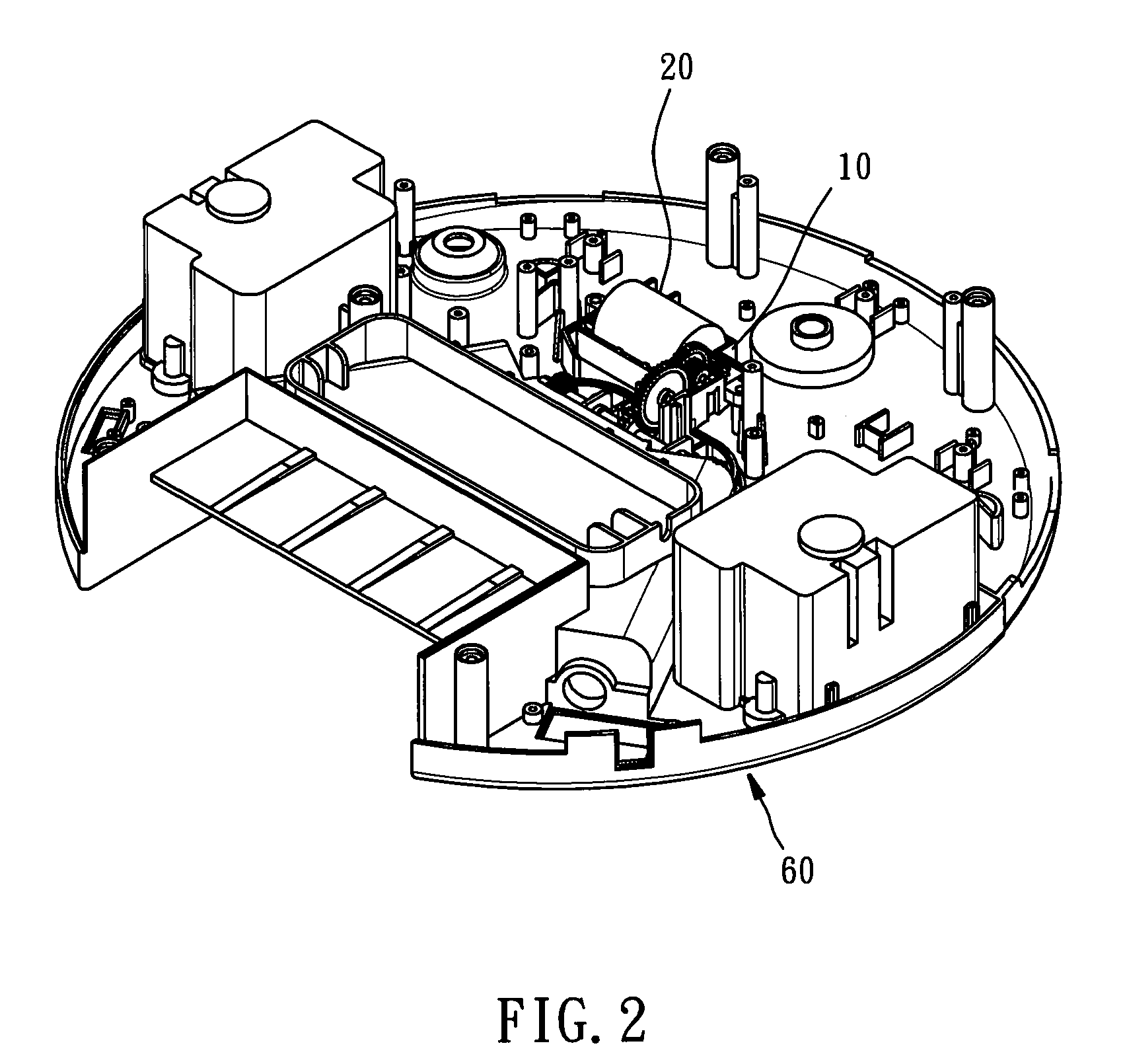
[0017]Referring to FIGS. 1-4, a driving module is shown installed in a base frame 60 having a power socket (not shown). The driving module comprises a casing 10, a motor 20, a transmission gear set 30, a transmission shaft 40 and at least one rotation shaft 50.

[0018]The casing 10 is detachably fastened to the base frame 60, defining therein an accommodation chamber 11.

[0019]The motor 20 is fixedly mounted in the accommodation chamber 11 inside the casing 10, having an output shaft 21 and a power cable (not shown) extending out of the casing 10 and electrically connected to the power socket.

[0020]The transmission gear set 30 is rotatable by the output shaft 21 of the motor 20 to transfer the rotary driving force of the motor 20 outwards.

[0021]The transmission shaft 40 is pivotally mounted in the casing 10, having a driving portion 41 and at least one, for example, but not limited to, two first toothed faces 42. The driving portion 41 is driven by the transmission gear set 30 to cause...


PUM


Abstract

A driving module installed in a base frame having a power socket is disclosed to include a casing detachably affixed to the base frame and defining therein an accommodation chamber, a motor fixedly mounted in the accommodation of the casing and having an output shaft and a power cable extended out of the casing and electrically connected to the power socket, a transmission gear set rotatable by the output shaft of the motor, a transmission shaft pivotally mounted in the casing and having a driving portion drivable by said transmission gear set to rotate the transmission shaft and at least one first toothed face, and at least one rotation shaft pivotally mounted in the casing, each rotation shaft having a second toothed face meshed with the first toothed face and rotatable by the transmission shaft.

Description

BACKGROUND OF THE INVENTION[0001]1. Field of the Invention[0002]The present invention relates to mobile robotic vacuum cleaner technology and more specifically, to a driving module installed in the base frame of the mobile robotic vacuum cleaner to rotate its roller brushes.[0003]2. Description of the Related Art[0004]Following improvement in living standards, modern people do more care about cleaning of home environment. Further, because people are busy with work, many different mobile robotic vacuum cleaners are created to serve people. To people who raise cats, dogs or other pets at home, the help of these mobile robotic vacuum cleaners is more prominent[0005]A mobile robotic vacuum cleaner has roller brushes mounted in the base frame thereof for direct contact with the floor below the base frame to direct dirty substances to a predetermined location for vacuuming. Gears and rotating shafts are pivotally mounted in the base frame and drivable by a motor to rotate the roller brush...

Claims


Application Information

Patent Timeline
IPC IPC(8): H02K7/116
CPCA47L9/0411A47L9/0433Y10T74/19084Y10T74/19Y10T74/19684A47L2201/00
Inventor FU, WANDA
Owner EGENPOWER
Why Eureka
Try Eureka