Systems and methods of accessory mounting

a technology of accessory mounting and support structure, applied in the field of supporting structure, can solve the problems that other accessories that may be of value to a user of an archery bow may not have been designed to be integrated, and the development may not have appreciated the relative positioning of accessories in relation to the weapon, so as to achieve uniform mounting structure

Inactive Publication Date: 2012-04-12
LANG RUSSELL W
View PDF41 Cites 22 Cited by
  • Summary
  • Abstract
  • Description
  • Claims
  • Application Information

AI Technical Summary

Benefits of technology

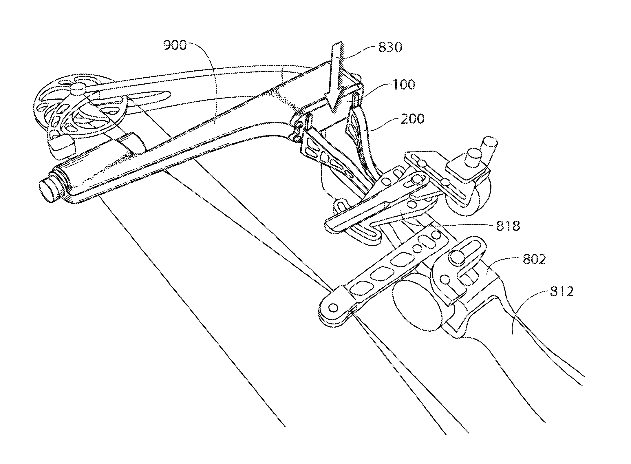
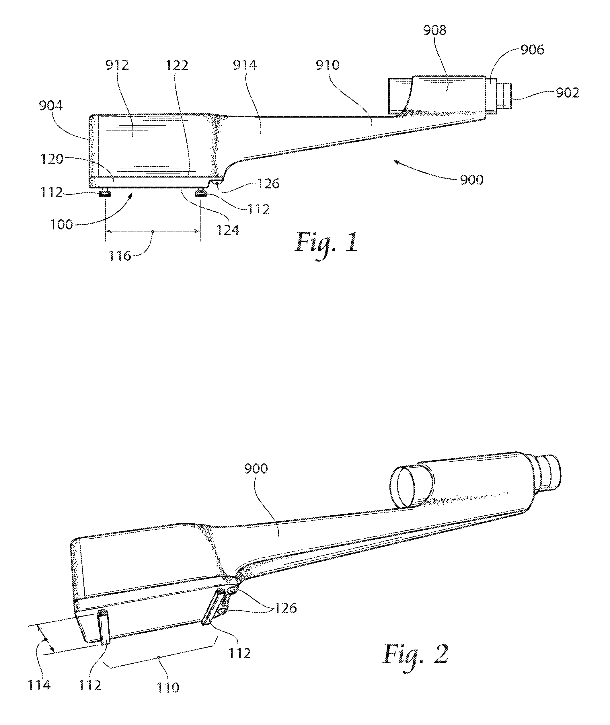
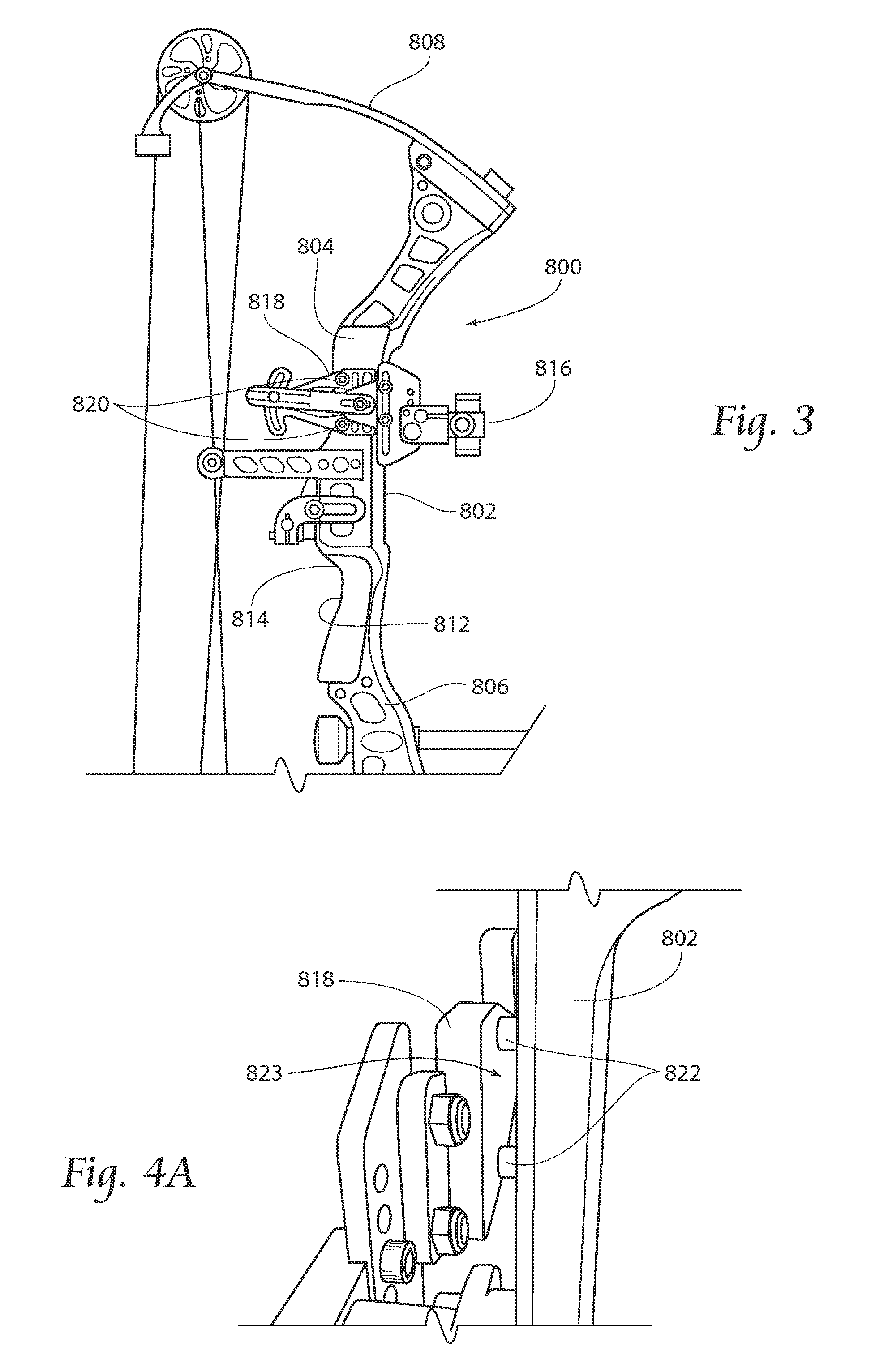
[0009]An apparatus according to the present invention provides an improved apparatus for positioning an accessory in relation to a support structure and to allow for uniform mounting structure to be provided on various weapons to allow for ease of transfer of an accessory from one weapon or support structure to another.

Problems solved by technology

However, other accessories that may be of value to a user of an archery bow may not have been designed to be integrated onto or supported by the bow.
While limited mounting locations may be provided on a rifle, other locations, and perhaps other accessories, that may be of value to a shooter may not have been designed to be integrated onto or supported by the rifle.
While devices and methods have been developed for supporting accessories on weapons and other structures, such developments may not have appreciated relative positioning of accessories in relation to the weapon, as well as desired interchangeability between mounting the same accessory on first an archery bow and then on a firearm, or vice versa.

Method used


Image

  • Systems and methods of accessory mounting
  • Systems and methods of accessory mounting
  • Systems and methods of accessory mounting

Examples


embodiment 710

[0074]FIG. 21 depicts an alternate embodiment 702 of a tubular support band, where like numbers refer to like structures in the prior embodiment 602. However, in this embodiment, the first section 710 and the second section 730 have been formed with a wraparound feature 770. The wraparound feature 770 may be formed in one or both of the sections 710,730 to accommodate for interruptive or disruptive features that may be provided on a tubular support member 868, such as the scope adjustment mechanism 872. Thus, while the prior embodiment featured a substantially circumferential band 602 provided along the entire length of the sections 610,630, this embodiment 710 may be used where the circumference of the tubular support member 868 is not continuous, but may be interrupted with other structures. Thus, the wraparound feature 770 may generally be formed as a notch or aperture formed into or through one or both of the sections 710,730. The first section 710 and second section 730 are pre...

embodiment 602

[0075]FIG. 22 shows an alternate embodiment 602′ of a mounting band according to the present invention, where the same numbers refer to the same structure as described in the previously described embodiment 602. This embodiment, however, uses an elastic latching structure 680 instead of the latching mechanism 650 described above. The elastic latching structure 680 generally includes two toggles 682 disposed on an elastic member 684 either immediately adjacent to each other or at a predetermined distance from one another. The toggles 682 are configured to rest in the top concave portions 614t,634t of the first section 610 and second section 630, respectively, while the elastic member 684 is configured to stretch between the toggles 682 and extend through the latch notch 620 on the first section 610 and the latch notch 640 on the second section 630. Also disposed on the elastic member 684, or on one of the toggles 682, is a handle member 686, which is configured to be grasped by the f...


PUM


Abstract

Embodiments according to the present invention provide improved systems and methods for mounting accessories, such as a rangefinder, to supporting structure, such as an archery bow or firearm. The improved accessory mount includes one or more brackets adapted to interface to the accessory and to the supporting structure. Preferred brackets provide universal adaptability between and amongst a variety of supporting structures.

Description

RELATED APPLICATIONS[0001]This application claims the benefit of co-pending U.S. Provisional Patent Application Ser. No. 61 / 404,944, filed 12 Oct. 2010, and entitled “Systems and Methods of Accessory Mounting.”[0002]This application is also a continuation-in-part of co-pending U.S. patent application Ser. No. 12 / 229,406, filed 22 Aug. 2008, and entitled “Archery Bow Accessory Mount,” which is incorporated herein by reference in its entirety.BACKGROUND OF THE INVENTION[0003]The present invention relates generally to the field of supporting structures, such as brackets and the like, and more particularly to the positioning and support of an accessory, such as a rangefinder, in relation to a weapon, such as an archery bow or a firearm, or other structure.[0004]Generally, an archery bow comprises a riser body and a pair of limbs extending from opposite ends of the riser body. Strung between the limbs is a bowstring. An archery bow may be provided as a compound bow or a long bow; a compo...

Claims


Application Information

Patent Timeline
Patent Type & Authority Applications(United States)
IPC IPC(8): F41B5/14
CPCF41B5/10F41B5/1484F41G11/004F41G1/473F41G1/467
Inventor LANG, RUSSELL W.
Owner LANG RUSSELL W
Why Eureka
Try Eureka