Touch display device

Active Publication Date: 2012-04-12
AU OPTRONICS CORP
View PDF4 Cites 54 Cited by
  • Summary
  • Abstract
  • Description
  • Claims
  • Application Information

AI Technical Summary

Benefits of technology

[0010]The invention is directed to a touch display device in which an optical touch module and a cover lid are in

Problems solved by technology

However, the display surface of the LCM 120 and the surface of the device housing 110 are not at the same horizontal level, which poses a negative impact on visual effects.
However, after the optical touch module 140 is additionally

Method used


Image

  • Touch display device
  • Touch display device
  • Touch display device

Examples


first embodiment

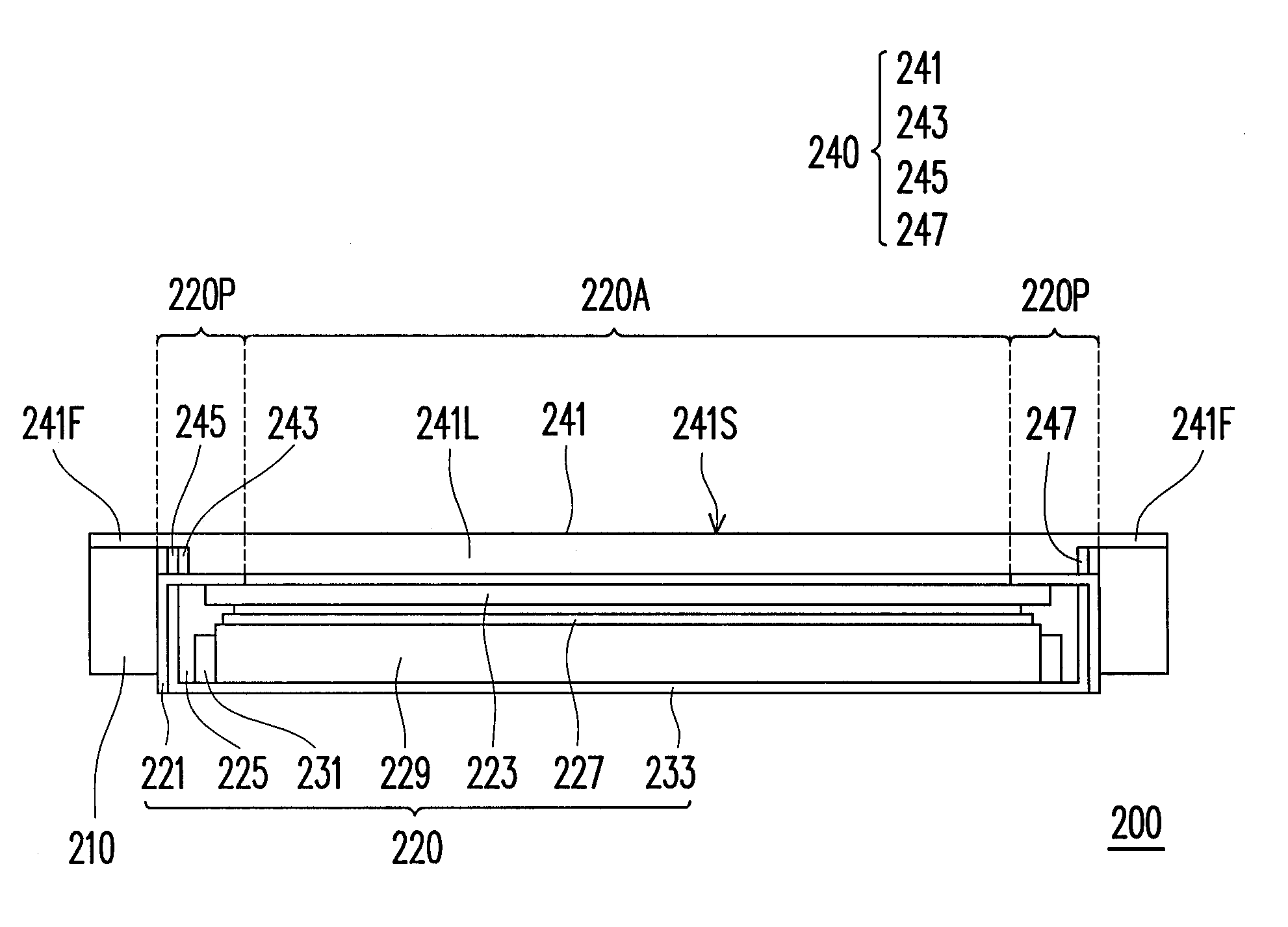
[0043]FIG. 2 is a schematic cross-sectional view illustrating a touch display device according to the invention. With reference to FIG. 2, in this embodiment, the touch display device 200 includes a device housing 210, a display module, and an optical touch module 240. Here, the display module is an LCM 220, for instance. The LCM 220 is configured within the device housing 210, and the LCM 220 has a display region 220A and a peripheral region 220P that surrounds the display region 220A. The optical touch module 240 is configured on the LCM 220.

[0044]The optical touch module 240 includes a light guide element 241, a light source 243, a photo sensor 245, and a reflector 247. The light guide element 241 has a top surface 241S. Here, the top surface 241S can be a flat surface. Besides, the light guide element 241 includes a light guide portion 241L located on the display region 220A and an outer frame portion 241F extending from an edge of the light guide portion 241L. The light guide p...

second embodiment

[0052]FIG. 5 is a schematic cross-sectional view illustrating a touch display device according to the invention. With reference to FIG. 2 and FIG. 5, the touch display device 500 is similar to the touch display device 200, while the difference therebetween lies in the front bezel 511 of the LCM 510. The front bezel 511 has a groove 511 a that accommodates the light source 243 and the photo sensor 245. Thereby, the light source 243 and the photo sensor 245 can be further secured, and the thickness of the light guide portion 241L can be reduced.

third embodiment

[0053]FIG. 6 is a schematic cross-sectional view illustrating a touch display device according to the invention. With reference to FIG. 2 and FIG. 6, the touch display device 600 is similar to the touch display device 200, while the difference therebetween lies in the device housing 610 and the frame 621 of the LCM 620. The device housing 610 has a groove 610a that accommodates the light source 243 and the photo sensor 245. Thereby, the light source 243 and the photo sensor 245 can be further secured. In this embodiment, the frame 621 replaces the front bezel 211 and the back bezel 233. Hence, the frame 621 holds and accommodates the LCD panel 223, the optical thin film 227, the light guide plate 229, and the backlight source 231. Like the front bezel 511, the frame 621 can also have a groove that accommodates the light source 243 and the photo sensor 245 in other embodiments of the invention. In this case, it is not necessary for the device housing 610 to have the groove 610a.

[005...


PUM


Abstract

A touch display device includes a device housing, a display module, and an optical touch module. The display module is located within the device housing and has a display region and a peripheral region surrounding the display region. The optical touch module is configured on the display module. Besides, the optical touch module includes a light guide element, a light source, and a photo sensor. The light guide element has a top surface and includes a light guide portion and an outer frame portion. The light guide portion is located on the display region. The outer frame portion extends from an edge of the light guide portion and is connected to the device housing. The light source supplies light to the light guide portion. The photo sensor receives the light from the light guide portion. The outer frame portion covers the light source and the photo sensor.

Description

CROSS-REFERENCE TO RELATED APPLICATION[0001]This application claims the priority benefit of Taiwan application serial no. 99134792, filed on Oct. 12, 2010. The entirety of the above-mentioned patent application is hereby incorporated by reference herein and made a part of this specification.BACKGROUND OF THE INVENTION[0002]1. Field of the Invention[0003]The invention relates to a touch display device. More particularly, the invention relates to an optical touch display device.[0004]2. Description of Related Art[0005]The increasing progress of display technologies brings about great conveniences to people's daily lives, and the demands for light and compact display devices contribute to the development of flat panel displays (FPDs) as mainstream displays. Among various FPDs, liquid crystal displays (LCDs) characterized by great space utilization, low power consumption, non-radiation, and low electromagnetic interference are prevailing.[0006]With advancement of information technology,...

Claims


Application Information

Patent Timeline
IPC IPC(8): G06F3/042
CPCG06F3/0428
Inventor CHIEN, CHIH-WEITSAI, SHAU-YU
Owner AU OPTRONICS CORP
Why Eureka
Try Eureka