Optical device
a technology of optical devices and terminals, which is applied in the direction of lighting and heating apparatus, electric apparatus casings/cabinets/drawers, instruments, etc., can solve the problems of limitation of the miniaturization of the terminals and the limitation of so as to increase the number of the terminal extended from the sidewall of the optical devi
- Summary
- Abstract
- Description
- Claims
- Application Information
AI Technical Summary
Benefits of technology
Problems solved by technology
Method used
Image

Examples
first embodiment
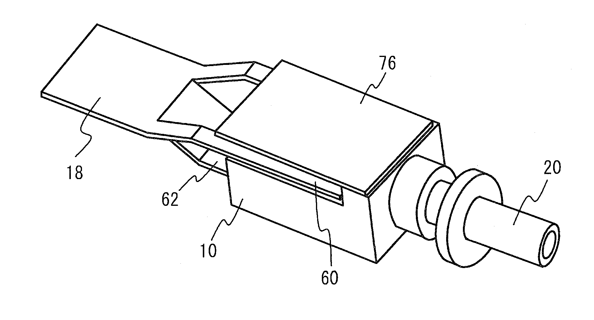
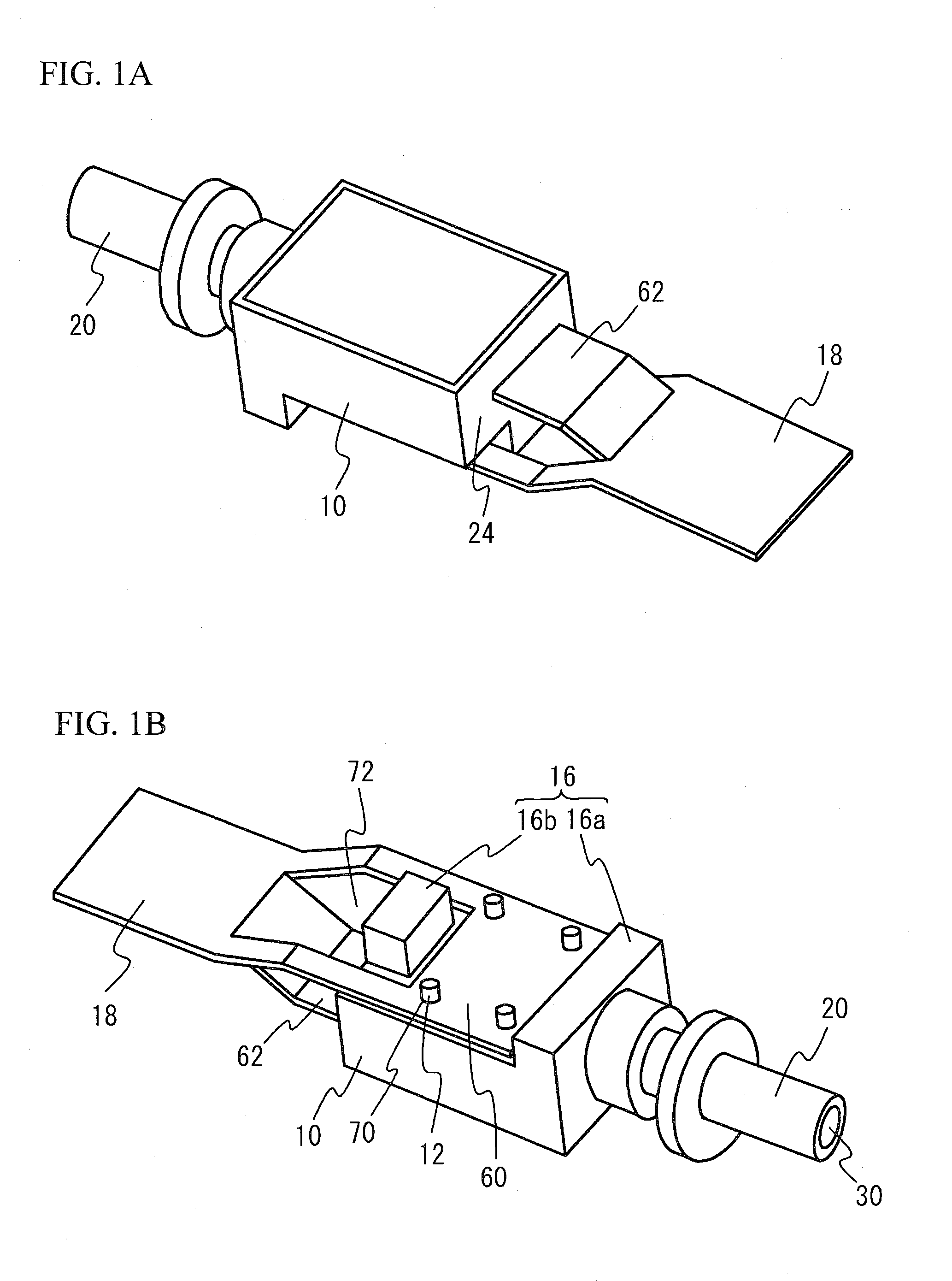
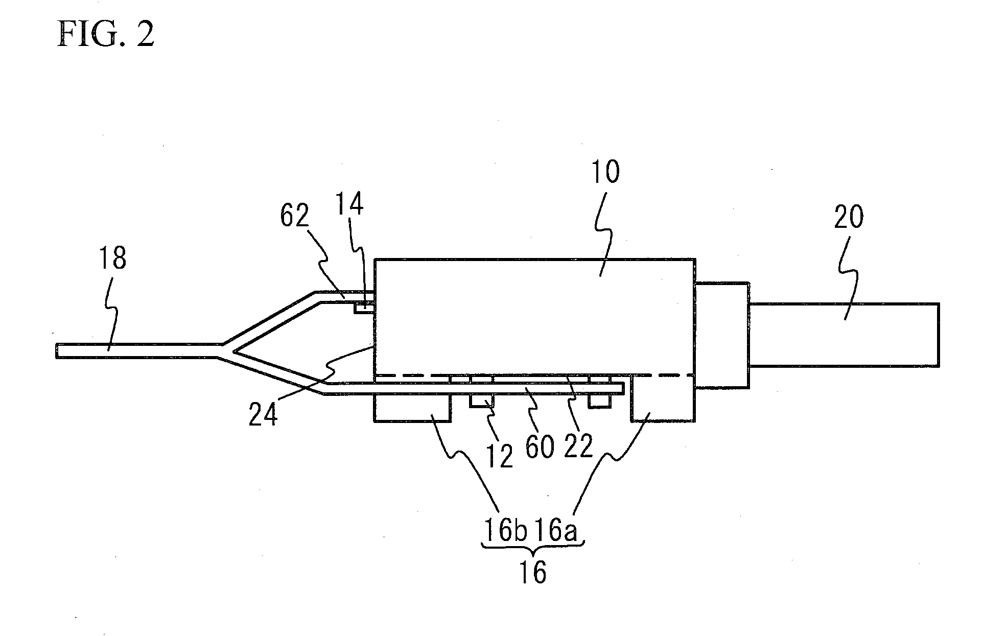
[0028]FIG. 1A illustrates a perspective view of an optical device in accordance with a first embodiment viewed from an upper face side. FIG. 1B illustrates another perspective view of the optical device viewed from a bottom face side. In FIG. 1A and FIG. 1B, a wiring pattern or a connector terminal formed on a flexible printed circuit board is omitted for simplification. FIG. 2 illustrates an example of a side view of the optical device. As illustrated in FIG. 1A through FIG. 2, the optical device in accordance with the first embodiment has a chassis 10, a first terminal 12, a second terminal 14, a projection portion 16, a flexible printed circuit board 18 and a receptacle 20. The chassis 10 houses an optical element therein that is a light-emitting element or a light-receiving element. The first terminal 12 penetrates a bottom wall of the chassis 10 and is extended from a bottom face 22 to outside. The second terminal 14 penetrates a sidewall that stands up with respect to the bott...
second embodiment
[0053]FIG. 10A illustrates a bottom view of an optical device in accordance with a second embodiment. FIG. 10B illustrates a bottom view of a flexible printed circuit board used in the optical device in accordance with the second embodiment. In FIG. 10A and FIG. 10B, wirings and connector terminals are not illustrated for simplification. As illustrated in FIG. 10A, the projection portion 16 of the optical device in accordance with the second embodiment includes the first projection portion 16a forming the same plane as the second side face 28 of the chassis 10 and the second projection portion 16b that forms the same plane as the first side face 24 of the chassis 10 and is divided into two parts at corners of the chassis 10.
[0054]As illustrated in FIG. 10B, the flexible printed circuit board 18 has the cutting line 58 including two of third cutting line portions 58c formed from each facing side face of the flexible printed circuit board 18 and two of fourth cutting line portions 58d...
third embodiment
[0056]FIG. 11A illustrates a bottom view of an optical device in accordance with a third embodiment. FIG. 11B illustrates a bottom view of a flexible printed circuit board used in the optical device in accordance with the third embodiment. In FIG. 11A and FIG. 11B, wirings and connector terminals are not illustrated for simplification. As illustrated in FIG. 11A, the projection portion 16 of the optical device in accordance with the third embodiment includes the first projection portion 16a forming the same plane as the second side face 28 of the chassis 10 and a third projection portion 16c extending toward the first side face 24 side from the second side face 28 side. That is, the projection portion 16 has T-shape.
[0057]As illustrated in FIG. 11B, the flexible printed circuit board 18 has the cutting line 58 including a fifth cutting line portion 58e and a sixth cutting line portion 58f. The fifth cutting line portion 58e includes a pair of first cutting line portions and a second...
PUM
 Abstract
Description
Claims
Application Information
 - R&D
- Intellectual Property
- Life Sciences
- Materials
- Tech Scout
- Unparalleled Data Quality
- Higher Quality Content
- 60% Fewer Hallucinations
Browse by: Latest US Patents, China's latest patents, Technical Efficacy Thesaurus, Application Domain, Technology Topic, Popular Technical Reports.
© 2025 PatSnap. All rights reserved.Legal|Privacy policy|Modern Slavery Act Transparency Statement|Sitemap|About US| Contact US: help@patsnap.com