DTX detection method and device

The technology of a detection method and detection device is applied in the field of DTX detection method and device, which can solve the problems of great difference in detection performance and low DTX accuracy.

Active Publication Date: 2017-03-22
COMBA TELECOM SYST CHINA LTD
View PDF5 Cites 0 Cited by
  • Summary
  • Abstract
  • Description
  • Claims
  • Application Information

AI Technical Summary

Problems solved by technology

[0004] The problem with the above method is: the optimal threshold value of DTX is greatly affected by the SNR of the environment, and changes with the change of the e

Method used


Image

  • DTX detection method and device
  • DTX detection method and device
  • DTX detection method and device

Examples


Embodiment 1

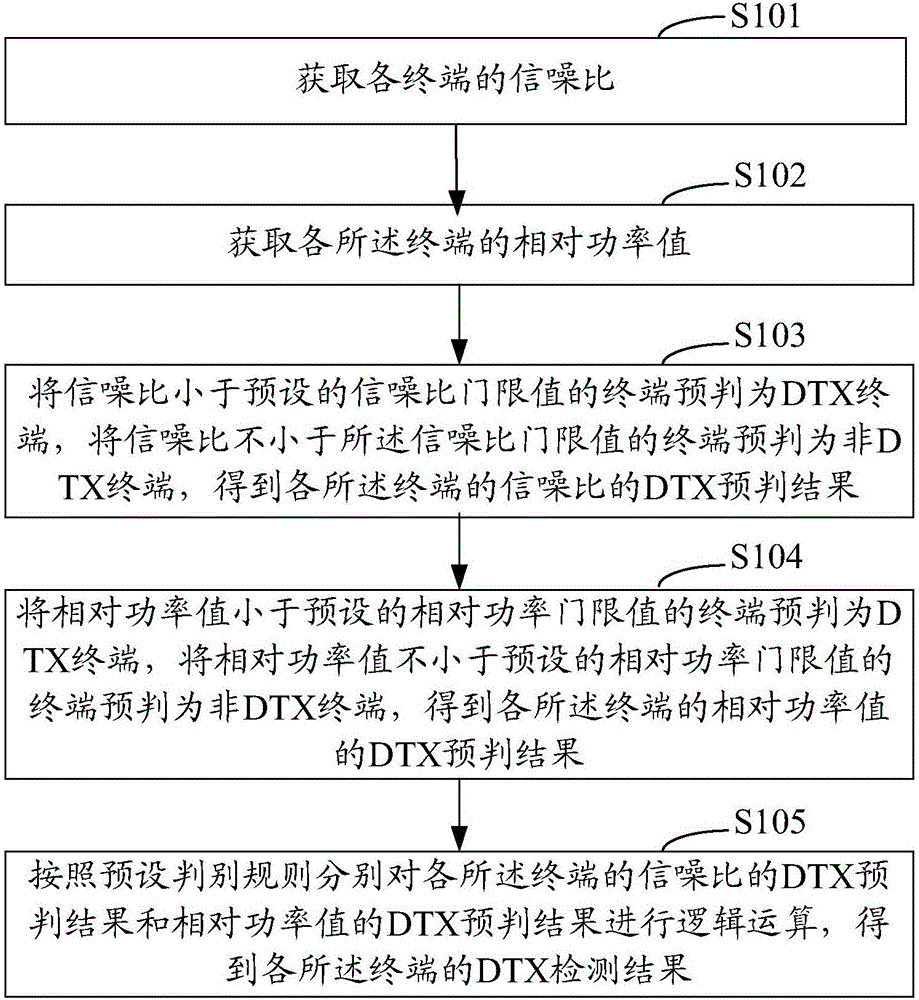
[0028] Embodiment 1 of the present invention provides a DTX detection method, see figure 1 As shown, it is a schematic diagram of the implementation process of the DTX detection method in Embodiment 1 of the present invention Figure 1 . Such as figure 1 As shown, the DTX detection method of the present embodiment 1 includes the following steps:

[0029] Step S101: Obtain the signal-to-noise ratio of each terminal;

[0030] Here, the signal-to-noise ratio of each terminal can be the ratio of the signal power value of the corresponding terminal to the noise power value, that is, SNR (Signal Noise Ratio), and the signal-to-noise ratio of each terminal can also be the signal power value of the corresponding terminal The ratio of the sum of the noise power value and the interference power value, SINR (Signal Interference Noise Ratio), considering that the noise power value and the interference power value are generally referred to as the noise power value, therefore, the signal...

Embodiment 2

[0097] According to the DTX detection method in the above embodiments, the present invention further provides a DTX detection device. Figure 4 It is a schematic diagram of the composition and structure of the DTX detection device of the second embodiment of the present invention Figure 1 . Such as Figure 4 As shown, the DTX detection device in Embodiment 2 includes a first parameter acquisition unit 401, a second parameter acquisition unit 402, a first pre-judgment unit 403, a second pre-judgment unit 404 and a comprehensive judgment unit 405, wherein:

[0098] The first parameter acquisition unit 401 is configured to acquire the signal-to-noise ratio of each terminal;

[0099] The second parameter acquisition unit 402 is configured to acquire the relative power value of each of the terminals;

[0100] The first predicting unit 403 is configured to predict a terminal whose signal-to-noise ratio is less than a preset signal-to-noise ratio threshold value as a DTX terminal...


PUM


Abstract

The present invention relates to a DTX detection method and system. The method comprises the following steps: acquiring the signal to noise ratio of each terminal; acquiring a relative power value of each terminal; pre-determining the terminal with signal to noise ratio smaller than a preset signal to noise ratio threshold as a DTX terminal, and pre-determining the terminal with signal to noise ratio not smaller than the preset signal to noise ratio threshold as a non-DTX terminal, and obtaining a DTX pre-determination result of the signal to noise ratio of each terminal; pre-determining the terminal with relative power value smaller than a preset relative power value threshold as the DTX terminal, and pre-determining the terminal with relative power value not smaller than the preset relative power value threshold as the non-DTX terminal, and obtaining a DTX pre-determination result of the relative power value of each terminal; and performing logic operation on the DTX pre-determination result of the signal to noise ratio of each terminal and the DTX pre-determination result of the relative power value of each terminal according to a preset pre-determination result to obtain a DTX detection result of each terminal. by adoption of the scheme provided by the invention, the accuracy of DTX detection can be improved.

Description

technical field [0001] The present invention relates to the technical field of wireless communication, in particular to a DTX detection method and device. Background technique [0002] In a wireless communication system, specifically in an LTE (Long Term Evolution, Long Term Evolution) system, during the uplink, the terminal uses the PUCCH (Physical Uplink Control Channel, Physical Uplink Control Channel) to send uplink scheduling signaling and downlink sharing to the base station. Channel ACK (Acknowledgment, confirmation character) / NACK (Negative ACKnowledgment, negative character) feedback information or channel quality indicator CQI (Channel Quality Indicator, channel quality indicator) feedback information. When the PUCCH feeds back the ACK / NACK feedback information of the downlink shared channel, the PDCCH (Physical Downlink Control Channel, physical downlink control channel) needs to be decoded first. If the terminal cannot correctly decode the PDCCH, the terminal wi...

Claims


Application Information

Patent Timeline
IPC IPC(8): H04W24/02H04W24/08
CPCH04W24/02H04W24/08
Inventor 吴顺妹付杰尉刁穗东
Owner COMBA TELECOM SYST CHINA LTD
Why Eureka
Try Eureka