
Microcatheter

Inactive Publication Date: 2012-04-12
EVR MEDICAL SARL
View PDF7 Cites 19 Cited by
  • Summary
  • Abstract
  • Description
  • Claims
  • Application Information

AI Technical Summary

Benefits of technology

[0018]Therefore, an object of this invention is to devise and make available an endolumenal device of the type specified above, which will meet the needs described above and, at the same time, make it possible to avoid all the pitfalls outlined.

Problems solved by technology

Such vessels can be very difficult to treat since they are very small and can only be reached through tortuous paths.
Also, when delivering an endolumenal device to a very small vessel through tortuous passages, an endolumenal device will often be in a random and non-optimal orientation.
Therefore, to be able to rotate the device when delivered is a problem.
Orienting an endolumenal device through such a passage is made more difficult by the tortuousity of the vessel segment.
Moreover, many catheters are single purpose and thus greatly enlarge inventory requirements for end users.
Moreover, many catheter devices are very complicated, which leads to greater cost.

Method used


Image

  • Microcatheter
  • Microcatheter
  • Microcatheter

Examples


Embodiment Construction

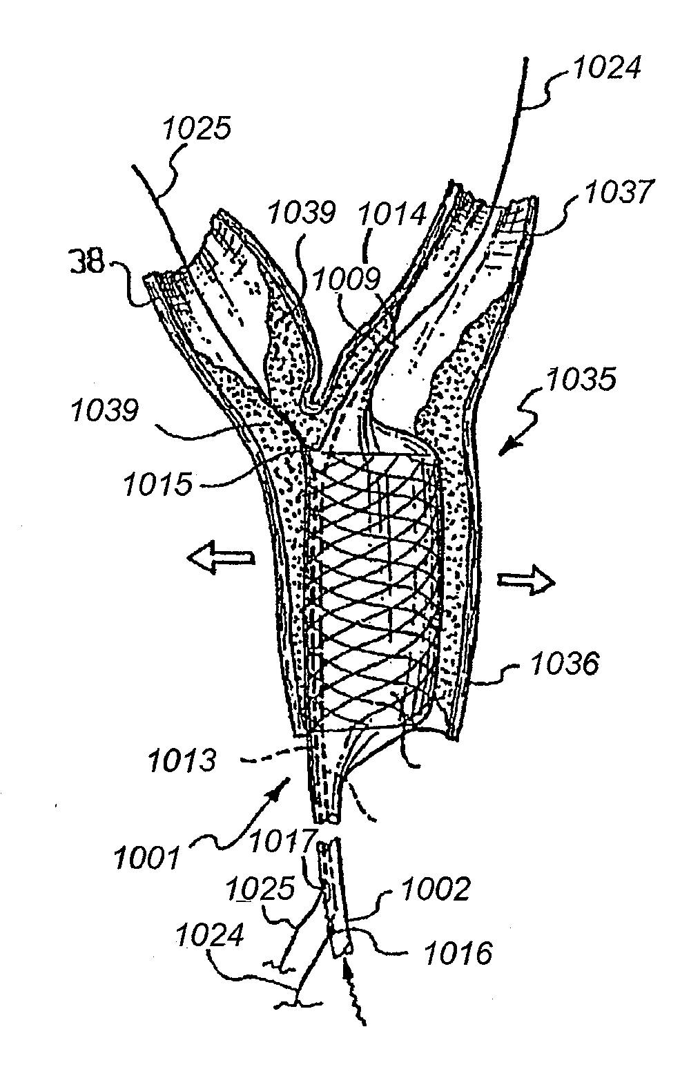
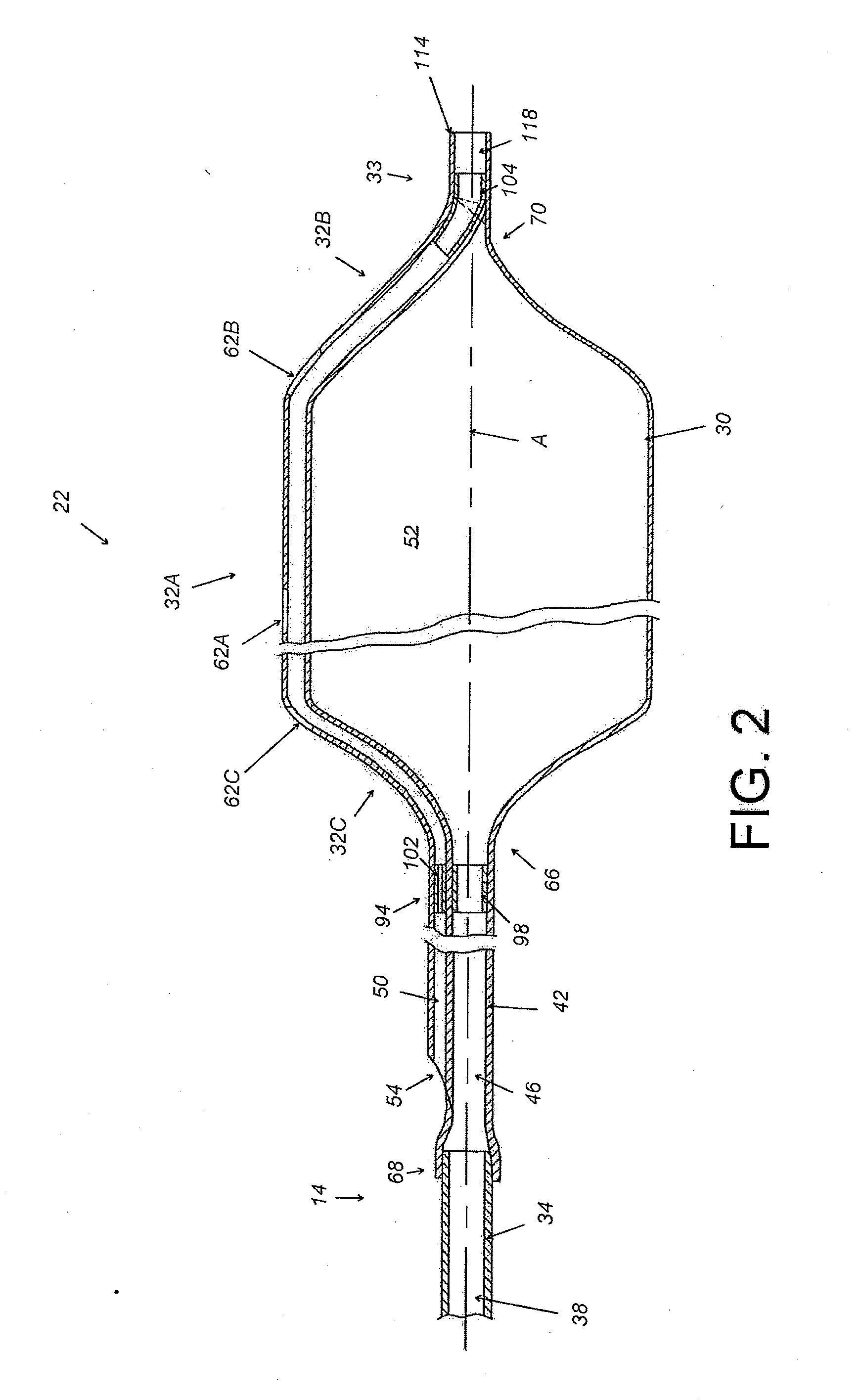
[0082]This application describes various embodiments of endovascular devices that can be used to access vessels at or adjacent to vascular bifurcations. Such devices that are particularly useful for smaller vessels are described in connection with FIGS. 1-16. Devices that are particularly useful for larger vessels are described in connection with FIGS. 17-79. Where the below disclosure is related to methods of use or manufacture, many concepts are applicable to all of the various endolumenal devices and such disclosure can be freely combined to provide for additional systems, kits, and methods, and modifications.

I. Catheter Apparatuses and Methods for Accessing Smaller Bifurcation and Vessels

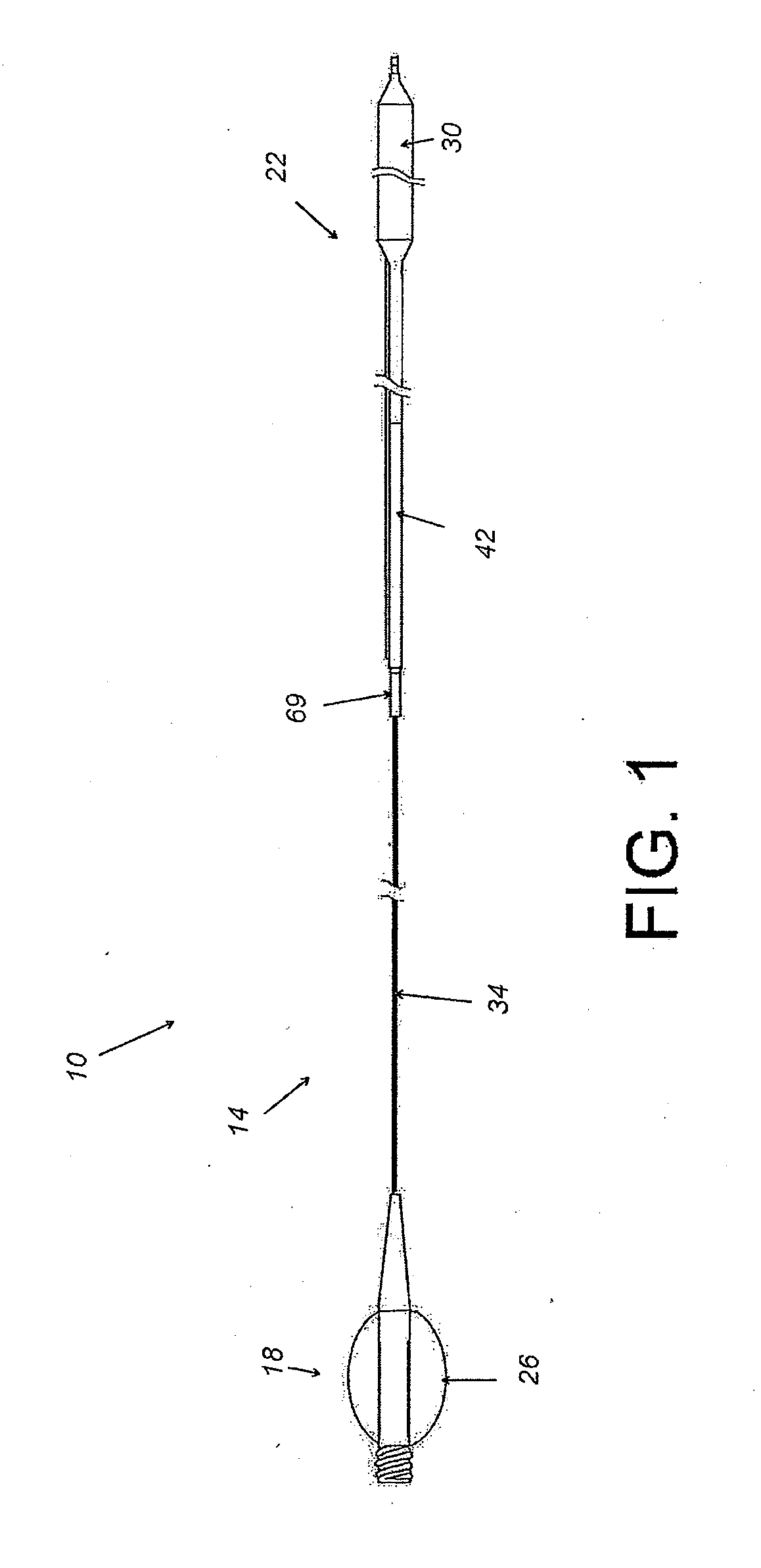
[0083]FIG. 1 shows an endolumenal device 10, commonly referred to as a catheter or a catheter assembly, that is useful in treating lesions at a vascular bifurcation. As will be discussed in greater detail below, the catheter assembly 10 is useful in very small blood vessels that cannot be treate...


PUM


Abstract

An endolumenal for delivering and positioning an endolumenal expandable prosthesis for a bifurcation is provided. The endolumenal device includes a guidewire tracking device and an elongated body that has a central longitudinal axis and an expansion device configured to expand symmetrically relative to the central longitudinal axis. The guidewire tracking device comprises a single guidewire lumen disposed within a wall structure of the expansion device. The guidewire tracking device has at least three distal ports extending through the wall structure of the expansion device. The guidewire lumen includes a distal apical port in an approximately central position relative to the expansion device, considered in cross section at right angles to the central longitudinal axis.

Description

CROSS-REFERENCE TO RELATED APPLICATIONS[0001]This application is a continuation-in-part of U.S. application Ser. No. 10 / 512,245, filed May 12, 2005, which is a U.S. National Phase of International Application No.: PCT / IB03 / 01178, filed Mar. 27, 2003 designating the U.S. and published in English on Oct. 30, 2003 as WO 03 / 088871, which claims the benefit of Italian Patent Application No. MI2002A000860, filed Apr. 22, 2002, and is a continuation-in-part of U.S. application Ser. No. 12 / 471,281, filed May 22, 2009, which is a divisional of U.S. application Ser. No. 10 / 204,251, filed Nov. 26, 2002, which is a U.S. National Phase of International Application No. PCT / EP00 / 13964, filed Dec. 19, 2000 designating the U.S. and published in English on Aug. 23, 2001 as WO 01 / 60284, which claims the benefit of Italian Patent Application No. 00200572.6, filed Feb. 18, 2000. Each of the applications listed above is incorporated by reference herein in its entirely.BACKGROUND OF THE INVENTIONS[0002]1....

Claims


Application Information

Patent Timeline
IPC IPC(8): A61F2/82
CPCA61F2/013A61F2/856A61F2/954A61M2025/107A61F2250/006A61M2025/1056A61F2/958
Inventor LUALDI, ALESSANDRO
Owner EVR MEDICAL SARL
Learn More