Hydroformylation process

Active Publication Date: 2016-09-08
JOHNSON MATTHEY DAVY TECH LTD +2
View PDF2 Cites 2 Cited by
  • Summary
  • Abstract
  • Description
  • Claims
  • Application Information

AI Technical Summary

Benefits of technology

[0012]Surprisingly, a process wherein the olefins are fed to separate trains that share a common product-catalyst separation zone a

Problems solved by technology

Inherent to co-feed operation are problems, compared to operations using 2 separate reactor trains, with balancing the reactors with variable feed rates, such as when one feed supply is reduced, and maintaining product isomer ratios.
In the first case, a reduction in the amount of the more highly reactive olefin, e.g., ethylene, greatly impacts heat generation, which may make the reactors unstable.
Conversely, a reduction in the amount of the less reactive olefin feed will give a first reactor enriched with highly reactive olefin and the reactor coolers may not be able to maintain steady state operation.
Changes in feed co

Method used


Image

  • Hydroformylation process
  • Hydroformylation process
  • Hydroformylation process

Examples


example 1

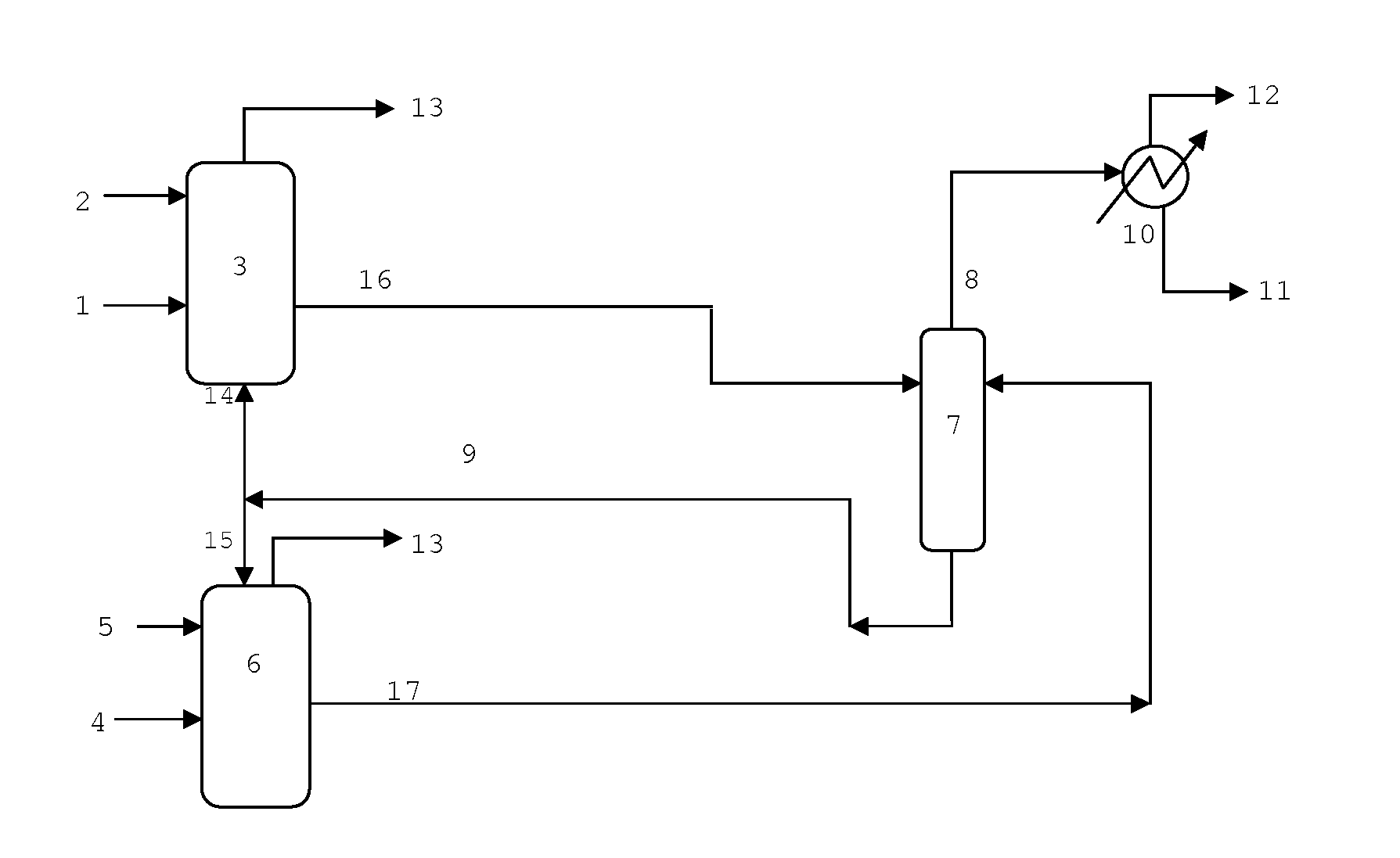
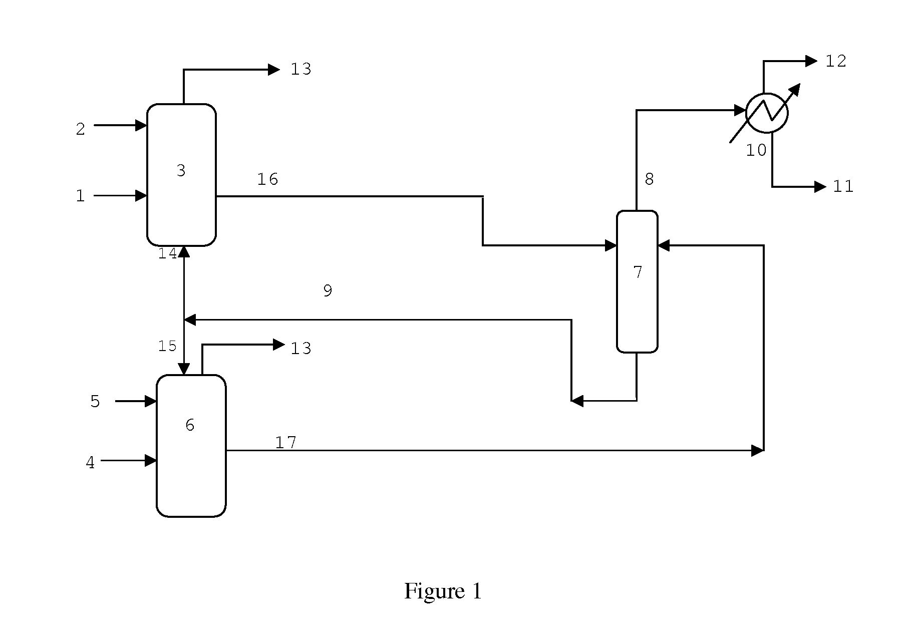
[0132]ASPEN Plus Dynamics™ process simulation software is used to develop an Oxo reaction system process control model for the process of FIG. 1. The catalyst is a typical Rh-bisphosphite catalyst as described in U.S. Pat. No. 4,668,651 and the reaction conditions are essentially those of Example 5 of that patent for butene-1 and Example 9 of that patent for propylene except for the following: a raffinate stream is employed rather than butene-1, the initial target rhodium concentration for the propylene train is 72 ppm Rh, and for the raffinate train the rhodium concentration design target is 260 ppm rhodium, with a Ligand:Rh ratio of >1 for both trains. These are efficient levels that would be used in conventional plants having two completely separate trains, giving high reaction rates, high conversions, and low ligand consumption at design rates for each train.

[0133]The basis for the modeling the reactor control system is as follows:[0134]1) The Oxo reaction rate is directly propo...

example 2

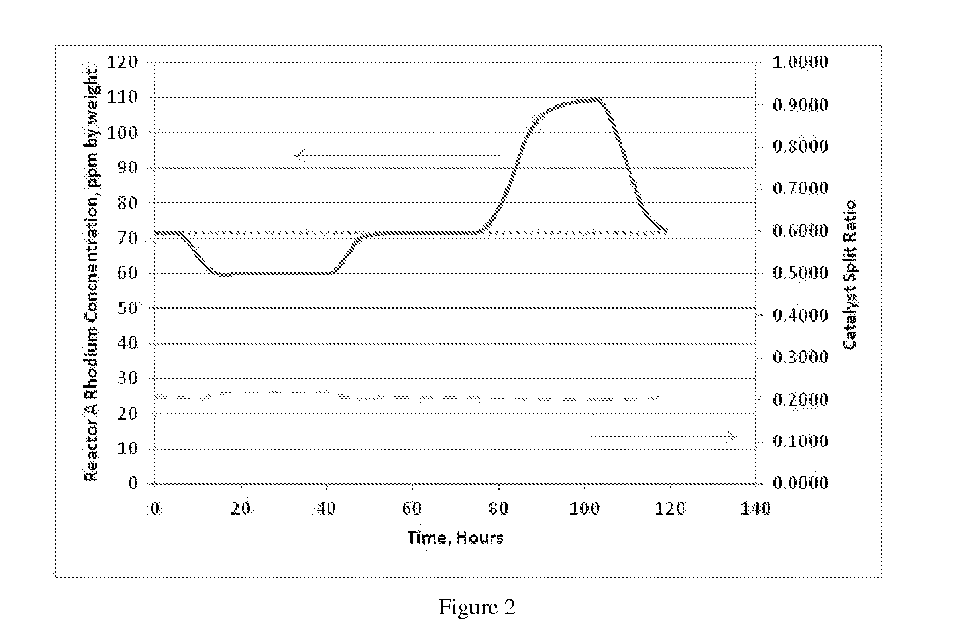
[0141]A series of ASPEN Plus Dynamics™ process simulations are performed using the process of Example 1 to demonstrate the effect of process disturbances on reactor behavior typically observed in commercial operation. These involve reductions in one feed or the other.

The sequence of process feed disturbances is as follows:[0142]Initially, Propylene and raffinate feed flow rates are at design flow rates.[0143]At time 4 hours, the raffinate feed flow rate begins a reduction to half of the design flow over a 6 hour ramp period.[0144]At time 10 hours, the raffinate feed flow is maintained at 50% of design rates.[0145]At time 40 hours, the raffinate feed flow rate begins a 6 hour increase returning to design rates.[0146]At time 46 hours, the raffinate is maintained at design flow rates.[0147]At time 75 hours, propylene feed flow rate begins a ramp for 50% reduction that takes 10 hours.[0148]At time 85 hours, the propylene feed is maintained at 50% of design flow rate.[0149]At Time 103 ho...

example 3

[0153]Example 2 is repeated except that a different control scheme is employed, as follows:

[0154]Maintain the propylene reactors, Reactor (3), at constant temperature and vary the catalyst recycle mass flow rate (stream (14)) to achieve the desired rhodium concentration. The purpose of the control scheme is to maintain the propylene reactors, Reactor (3), at constant reactivity and vary the catalyst recycle mass flow rate (stream (14)) to achieve the desired rhodium concentration. The approach is to “infer” the Reactor (3) rhodium concentration based on the overall material balance and physical volume and geometry of the Oxo reaction system from which the control change is determined. Since the total rhodium inventory is known and fixed, the effect of changes in the operation of each reactor train can be used to predict the performance. The primary variable for each reaction train is the olefin feed, propylene and raffinate for reactors (3) and (6), respectively.

[0155]The control sc...


PUM

PropertyMeasurementUnit
Temperatureaaaaaaaaaa
Partial pressureaaaaaaaaaa
Pressureaaaaaaaaaa

Abstract

A multi-reaction train hydroformylation process wherein a common product-catalyst separation zone is employed.

Description

BACKGROUND OF THE INVENTION[0001]The invention relates to a process for the hydroformylation of olefins to produce aldehydes.[0002]It is often desirable to feed two or more olefins at the same hydroformylation facility. In some cases, both olefins are fed to the same reactor. This process, commonly referred to as a “co-feed” process, allows capital savings compared to having separate, complete production trains for each olefin. The co-feed process shares a hydroformylation reactor and product-catalyst separation equipment, and then downstream refining separates the products for further processing. Examples of this process are disclosed in EP 0 052 999, GB 1,120,277, WO 1980 / 001691, U.S. Pat. No. 4,262,142, Ex. 13 of U.S. Pat. No. 4,400,547 and U.S. Pat. No. 5,312,996.[0003]Inherent to co-feed operation are problems, compared to operations using 2 separate reactor trains, with balancing the reactors with variable feed rates, such as when one feed supply is reduced, and maintaining pr...

Claims


Application Information

Patent Timeline
IPC IPC(8): C07C45/50B01J31/24C07C45/78
CPCC07C45/50C07C45/78B01J2531/822B01J2231/321B01J31/24C07C45/82Y02P20/582C07C47/02
Inventor EISENSCHMID, THOMAS C.MOKHTARZADEH, MORTEZASMITH, III, CLOID R.BECKER, MICHAEL C.PHILLIPS, GEORGE R.BRAMMER, MICHAEL A.MILLER, GLENN A.WATSON, RICK B.COX, IRVIN B.LORD, EDWARD A.SMIDT, MARTIN LUCAS
Owner JOHNSON MATTHEY DAVY TECH LTD
Why Eureka
Try Eureka