Telescopic lifting device with safety strap

a technology of safety straps and lifting devices, which is applied in the direction of safety devices, lifting devices, lifting frames, etc., can solve problems such as the winch system

Active Publication Date: 2014-08-19
TALBOT DECOUPAGE EMBOUTISSAGE
View PDF3 Cites 2 Cited by
  • Summary
  • Abstract
  • Description
  • Claims
  • Application Information

AI Technical Summary

Benefits of technology

[0005]The invention is aimed at avoiding these pitfalls by means of a lifting device with a telescopic pole in which the force exerted by the operator turning the crank handle that adjusts the height of the telescopic pole is directly transmitted to the sliding connection between two different modules, without having to use a cable wound in successive coils around a winch reel. No longer using a cable wound around a winch eliminates a major disadvantage of the winch system arising from variations in the force exerted by the operator to lift a given load over a given distance. The length of cable which must be pulled by the operator each time depends on the developed length of the turn, which varies according to the number of successive turns on the winch reel around which the cable is wound.
[0007]The invention identified in the present European patent application, on the other hand, refers to a lift device in which the drive force is transferred by a strap which is also completed with a safety device so that the use of the telescopic system is made particularly safe for the operator.
[0009]Operation of the safety device associated with the strap is based on whether or not the strap is taut. It entails a locking system to prevent displacement of the upper module which stops it from moving with respect to the previous module if the strap breaks (or is no longer taut). The locking system above is usefully maintained in inactive position during normal operation by the effect of the taut strap on a lever subjected to the elastic return action of a spring. As soon as the strap breaks, the active position is automatically triggered to prevent continuing displacement of the upper module with respect to the intermediate module which immediately precedes it in a telescopic stage with three successive modules.
[0010]A passive locking system is thus usefully obtained which is particularly effective because it is activated as soon as the strap breaks, and its implementation and removal cannot be forgotten unintentionally.
[0012]The safety device in the event of breaking of the strap comprises a locking system to prevent displacement of the module which is hinged to the module with respect to which it slides and maintained in inactive position by the tautness of the strap counteracting the force of a return spring pushing the locking system towards its active position;

Problems solved by technology

No longer using a cable wound around a winch eliminates a major disadvantage of the winch system arising from variations in the force exerted by the operator to lift a given load over a given distance.

Method used


Image

  • Telescopic lifting device with safety strap
  • Telescopic lifting device with safety strap
  • Telescopic lifting device with safety strap

Examples


first embodiment

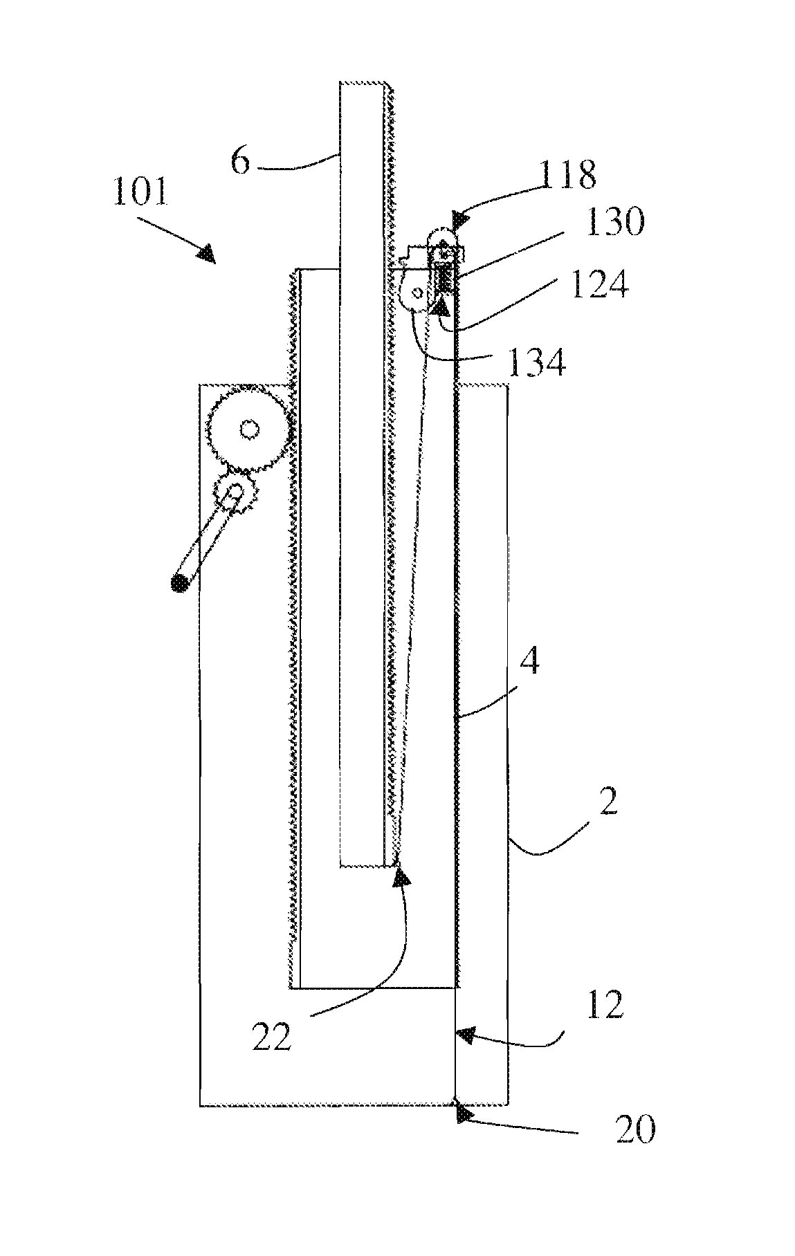
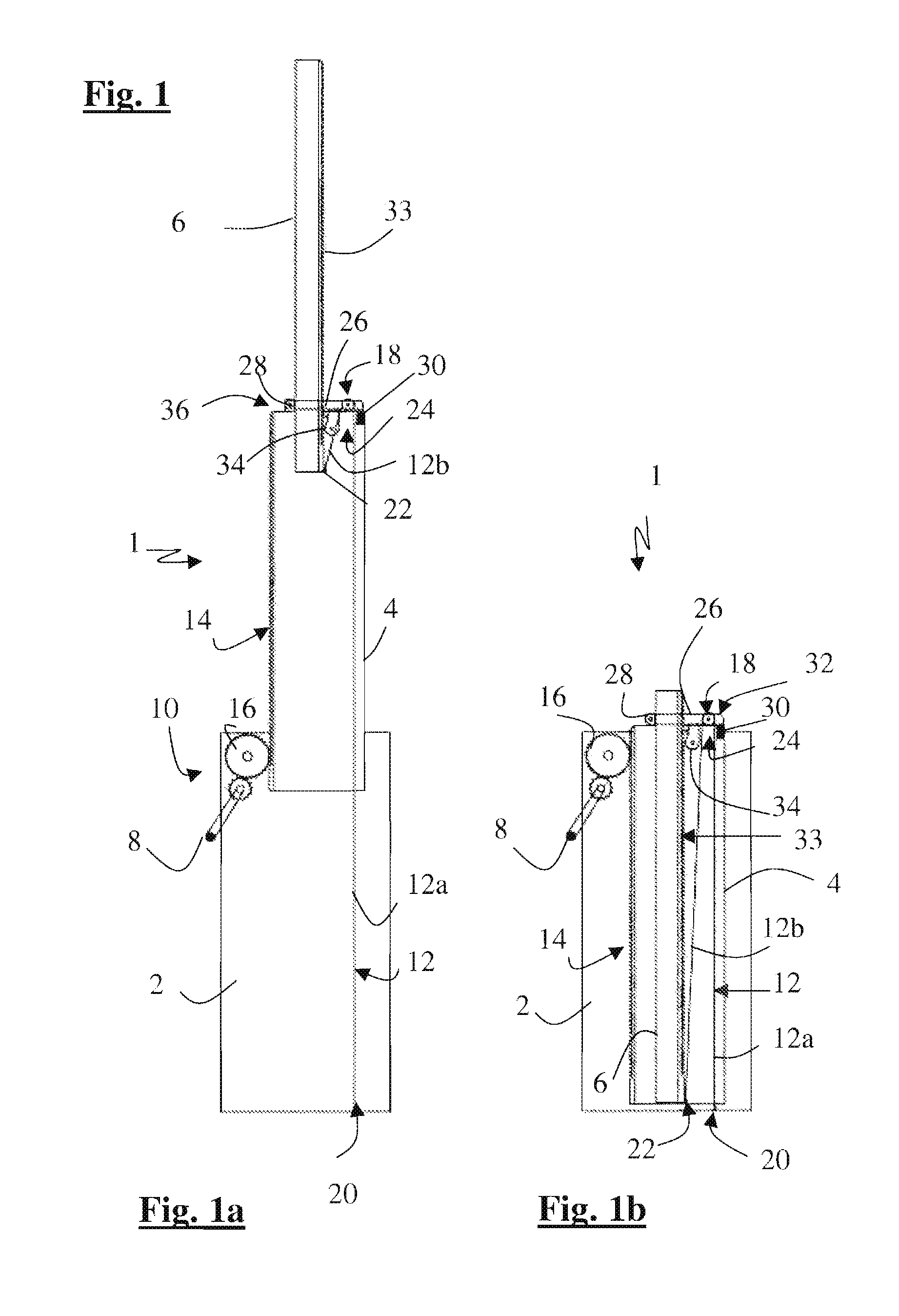
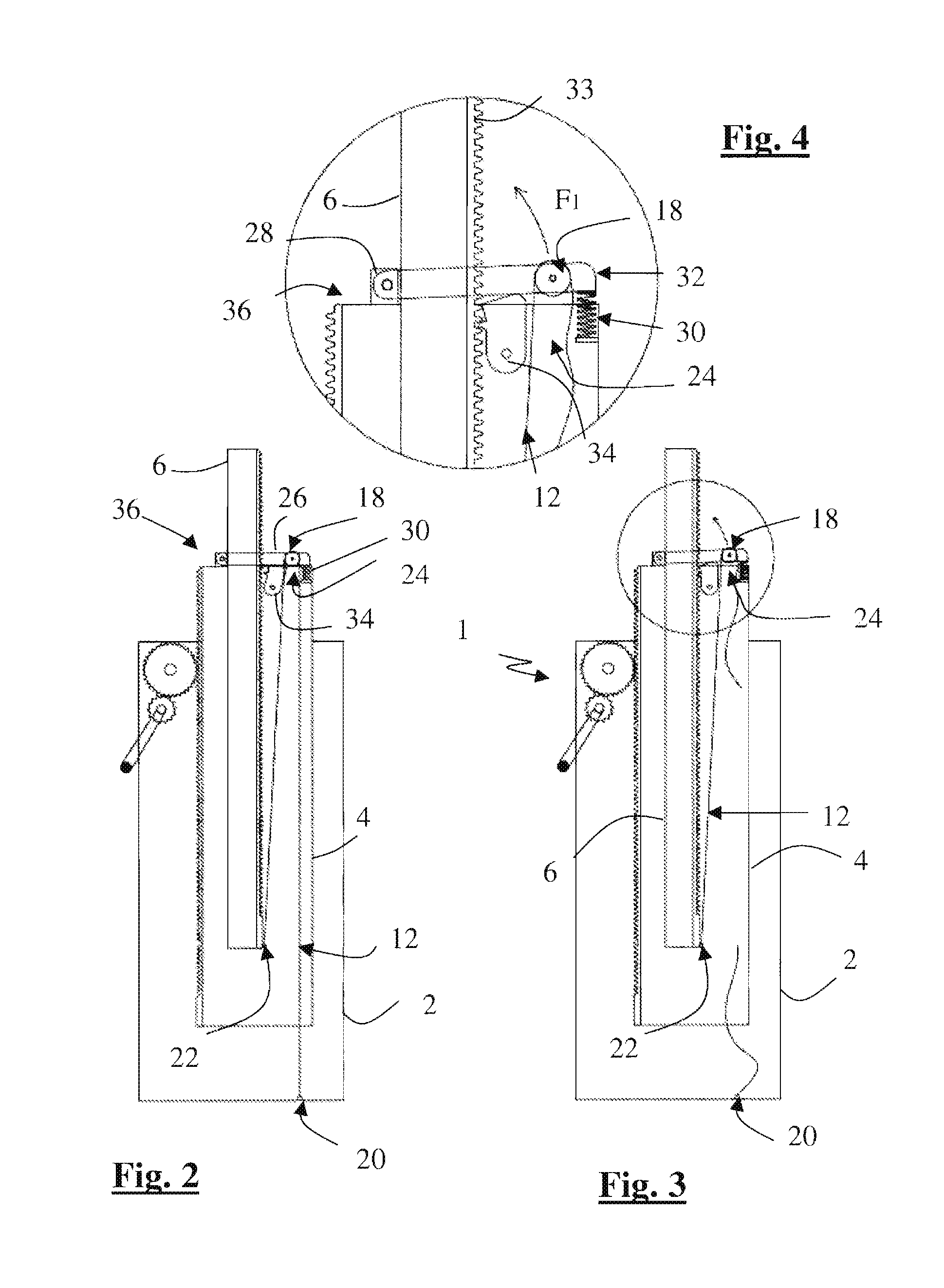
[0035]In the telescopic load lifting device as illustrated in FIGS. 1 to 4, the lifting device 1 comprises a last module 6 which is slidably movable along the previous intermediate module 4, and a base module 2 along which the said intermediate module 4 is designed to slide.

[0036]The three modules together form a telescopic stage whose extension is obtained by turning the crank handle 8 and by the combination of a rack and pinion 10 and a return strap 12.

[0037]The rack and pinion is used between the base module and the intermediate module. It can be described briefly as follows.

[0038]A gear reduction system connected to the crank handle (which can be fixed or removable) directly drives a rack 14 on the intermediate module. This is coupled with a self-locking friction brake system so that the position of the intermediate module sliding in relation to the base module is maintained whether the crank handle is activated or not. This system can be directly incorporated into the tube or m...

third embodiment

[0060]We will now describe a third embodiment for the invention illustrated in FIGS. 8 to 12. In accordance with the previous methods, the lifting device 201 comprises a three-module pole which has a rack on the last module and a safety system and strap return system on the intermediate module. Here, the safety system 224 comprises a pawl forming a locking system 234 which is hinged to the intermediate module, between an inactive position (FIGS. 9 and 10) in which the pawl is not engaged with the rack and does not prevent it from moving, and an active position (FIG. 8) in which the pawl is engaged with the rack to lock the last module in place. The pawl is directly pushed by the return spring 230 which tends to hold the pawl against the rack.

[0061]The free end of the pawl, opposite the end with the locking pin, is connected to a controller handle 231 by means of a cable 233, in a similar mounting to that of a bicycle brake cable. Pressure on the controller handle pulls the cable tow...

fourth embodiment

[0065]We will now describe a fourth embodiment for the invention, illustrated in FIGS. 13 to 15, which differs from the first method described above in that the safety system 324 does not lock the last module in place by means of a pawl but by jamming the extruded section of the module itself. The guard 326 is mounted so as to be pivotal around a spindle 328 solid with the intermediate module, but is adjusted to fit around the last module. The opening through which the last module passes is dimensioned so that, when the guard tilts under the action of the spring after the strap breaks, the sides of the opening will push against the third tube and prevent it from sliding into the opening. This is where the guard plays the role of a locking system designed to prevent the module from moving under the force of the return spring released by the breaking of the strap. As a result, as illustrated in the figures, the last module does not need to be equipped with a rack.


PUM


Abstract

A lifting device with a telescopic pole having at least three successive modules mounted so that the modules can slide vertically with respect to each other. A drive strap transfers movement in order to extend an upper module with respect to an intermediate module when the intermediate module is caused to move with respect to a lower module of the modules. The drive strap is kept taut between two fixation points placed respectively on the lower module and upper modules and pass along a return pulley device mounted on the intermediate module. A safety system is normally maintained in inactive position by tension of the drive strap is automatically released into active locking position to prevent the upper module from continuing to move with respect to the intermediate module if the drive strap breaks.

Description

BACKGROUND[0001]This invention concerns the design and construction of a lifting device with a telescopic pole which is at least partly of the strap lift type. The device can vertically displace a load over several meters. It consists of a telescopic pole that can be equipped, as needed, at the base, with a stand system and, at the top, with any system that will allow the load to be attached or handled.[0002]Telescopic lifting devices already exist which comprise modules that slide vertically over each other and in which the movement of an upper module with respect to a lower module is obtained by one or several cables connecting up the modules. Extension of the system and vertical displacement of the load attached to the upper module are obtained by means of a tensile force exerted on the crank handle of a winch fixed to the outside of the lower module and the base of the device and to which the end of one of the cables is connected.[0003]To meet safety standards, mechanical means ...

Claims


Application Information

Patent Timeline
Patent Type & Authority Patents(United States)
IPC IPC(8): B66D1/36
CPCB66F3/00B66F7/02B66F17/00
Inventor GUYARD, FRANCOIS-XAVIER
Owner TALBOT DECOUPAGE EMBOUTISSAGE
Why Eureka
Try Eureka