
Compact multi-motion lifting and transferring apparatus and method of operating same

a multi-motion, lifting and transferring technology, applied in vehicle components, vehicle arrangements, ambulance services, etc., can solve the problems of difficulty in transferring disabled persons from one location, cost and complexity, and difficulty in lifting and transferring such persons to and from their wheelchairs

Active Publication Date: 2012-04-19
EGAN THOMAS F
View PDF26 Cites 18 Cited by
  • Summary
  • Abstract
  • Description
  • Claims
  • Application Information

AI Technical Summary

Benefits of technology

[0011]In accordance with further aspects of the present disclosure, in the case of the slide tray version, the slide tray may be secured by a latching mechanism which allows for entry of a latch striker from a rearward direction. It may also provide an intermediary latching position, and incorporate a slot which allows additional travel towards the rear of a vehicle, which can be useful in vehicles with minimal legroom where a user may benefit from an initial rearward motion of the seat to allow leg exit prior to rotation and exit.
[0015]In accordance with still further aspects of the present disclosure, the electrically or hydraulically-actuated rotators and actuators may comprise in their control circuitry a door sensor electrical or optical switch, which may prevent operation of the apparatus when the vehicle door is closed.
[0016]In accordance with still further aspects of the present disclosure, the electrically actuated rotators may comprise in their control circuitry electrical current load sensors, which may prevent rotation or up-down motion of the apparatus when a barrier such as a human body part or other obstacle is encountered.
[0017]In accordance with still further aspects of the present disclosure, rotation, sliding, and up-down motion may incorporate control circuitry optical sensors or electrical switches, which may prevent rotation of the apparatus when a barrier such as a human body part or other obstacle is encountered in key obstruction areas.
[0020]In accordance with still further aspects of the present disclosure, one or more of the electrically actuated rotators and the electrical extension arms may include limit switches for preventing excessive movement and / or rotation inward or outward or upwards or downward.

Problems solved by technology

Difficulties are often encountered when transferring disabled persons from one location to another.
Particularly in the case of wheelchair-bound persons, it is often quite difficult to lift and transfer such persons to and from their wheelchair from and to, for example, a motor vehicle.
However, the devices disclosed in these patents, as well as other known devices, have drawbacks in the areas of cost and complexity which could limit the potential mobility of a disabled individual.
Also, the device disclosed in U.S. Pat. No. 6,223,364 is incompatible with the functional and installation requirements of certain combinations of vehicles and users, in particular when a vehicle has a relatively small door opening and structural obstructions in the exit path of the seat, when users require extra legroom and a rearward motion of the seat prior to turning and exit.
However, this product does not overcome many vehicle structures and other obstructions if the seat is exiting the vehicle.
Similar drawbacks exist for other known lifting and transferring devices.
For example, the lift and transport apparatus disclosed in U.S. Pat. No. 7,862,287 has the disadvantage of a complex set multiple pivot points, which make it difficult to achieve structural stability while keeping within industry standard lift weight requirements.
This presents severe challenges as the design of modern vehicles favors larger seats in smaller vehicles and thus reduces empty space adjacent to the seats available for such a drive mechanism.
In view of the foregoing, it may be understood that there may be significant problems and shortcomings associated with current lifting and transferring apparatuses for assisting persons when entering and exiting a vehicle.

Method used


Image

  • Compact multi-motion lifting and transferring apparatus and method of operating same
  • Compact multi-motion lifting and transferring apparatus and method of operating same
  • Compact multi-motion lifting and transferring apparatus and method of operating same

Examples


Embodiment Construction

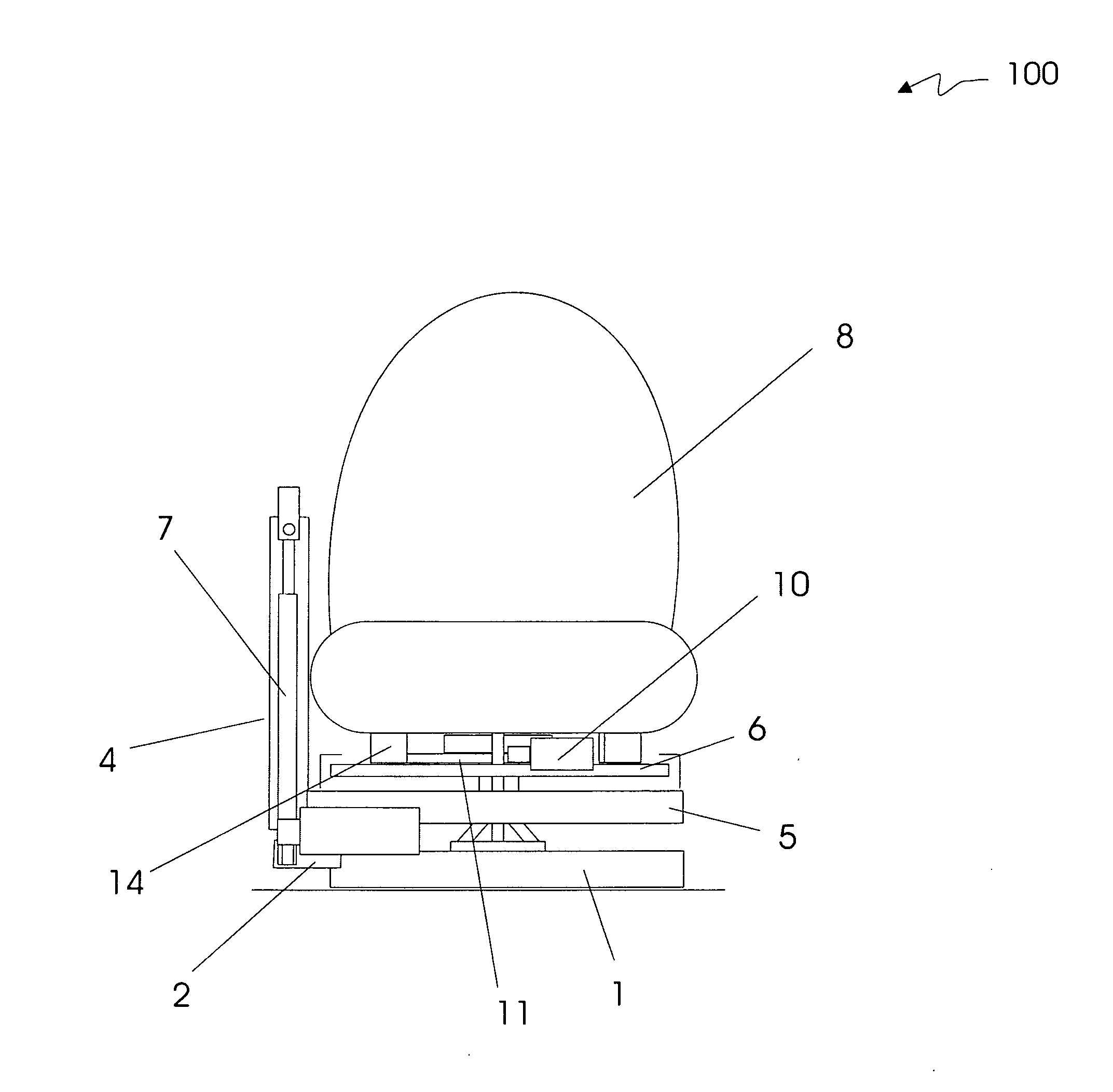
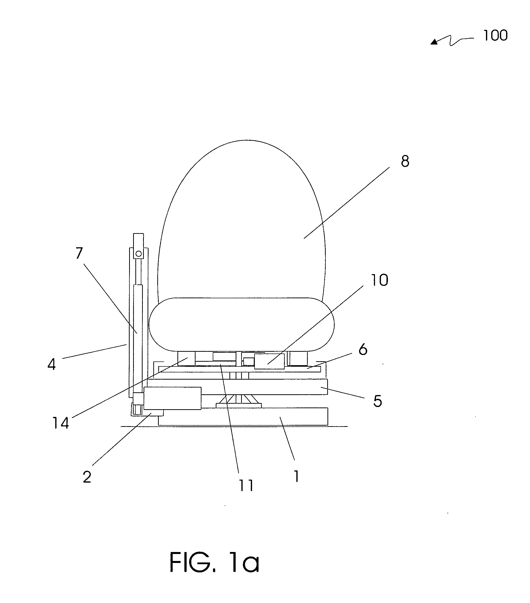
[0029]Referring to FIGS. 1A-1C, there is shown a multi-motion lifting and transferring apparatus 100 in accordance with an embodiment of the present disclosure in three respective views, front, side and rear. Beginning from the bottom of the apparatus 100 upward, the apparatus 100 includes a base support plate 1 for securely mounting the apparatus 100 to, for example, the floor of a vehicle or other structure. The apparatus 100 also includes a pivot point 2 allowing lower up / down extension arm assembly 3, upper up / down extension arm assembly 4, seat support assembly 5, slide tray assembly 6, up / down drive assembly 7, and seat 8 to pivot about a substantially vertical axis unless impaired by vehicle structural elements or interference from other apparatus structures.

[0030]Lower up / down extension arm assembly 3 supports, interlocks with, and provides a sliding contact surface for upper up / down extension arm assembly 4. Seat support assembly 5 is firmly attached to upper up / down extens...


PUM


Abstract

A compact multi-motion lifting and transferring apparatus and a method of operating same are disclosed. In one particular embodiment, the apparatus may comprise an intermediary support member configured to be rotated about a substantially vertical axis, an electrically or hydraulically powered up / down extension arm, a support member for supporting a seat for accommodating at least one person, and a latching mechanism for securing the seat and seat support mechanism in a fully stowed position suitable for traveling in a vehicle.

Description

CROSS-REFERENCE TO RELATED APPLICATIONS[0001]This patent application claims priority to U.S. Provisional Patent Application No. 61 / 344,489, filed Aug. 5, 2010, which is hereby incorporated by reference herein in its entirety.FIELD OF THE DISCLOSURE[0002]The present disclosure relates generally to devices and methods for lifting and transferring persons into and out of vehicles and, more particularly, to a compact multi-motion lifting and transferring apparatus and a method of operating same for assisting persons when entering and exiting a vehicle.BACKGROUND OF THE DISCLOSURE[0003]Difficulties are often encountered when transferring disabled persons from one location to another. Particularly in the case of wheelchair-bound persons, it is often quite difficult to lift and transfer such persons to and from their wheelchair from and to, for example, a motor vehicle. One or more persons are usually required to assist the disabled person.[0004]There have been some inventive efforts direc...

Claims


Application Information

Patent Timeline
IPC IPC(8): B60N2/16B60N2/06B60N2/14
CPCB60N2/0232B60N2/245B60N2/14B60N2/06B60N2/02246B60N2/146A61G3/062B60N2/0742
Inventor EGAN, THOMAS F.
Owner EGAN THOMAS F
Learn More