Measurement method and measurement system for measuring birefringence

a measurement method and measurement system technology, applied in the direction of optical radiation measurement, optical apparatus testing, instruments, etc., can solve the problem of relatively few sufficiently transparent materials available for producing transparent optical elements, and achieve the effect of high-precision measurement of small values

Active Publication Date: 2012-04-19
CARL ZEISS SMT GMBH
View PDF1 Cites 33 Cited by
  • Summary
  • Abstract
  • Description
  • Claims
  • Application Information

AI Technical Summary

Benefits of technology

[0020]It is one object of the invention to provide a measurement method for measuring birefringence which permits a highly precise measurement of small values of birefringence. In particular, the measurement method is intended to have a measurement accuracy of less than 0.5 nm for small birefringence values.

Problems solved by technology

On the other hand, in many demanding applications, for example in the field of microlithography, laser optics or astronomy, the birefringence of optical components is treated as an undesirable cause of error and endeavours are made to minimize the influence of birefringence on the optical properties of optical components or optical systems and / or to know it at least precisely enough that compensation is possible.
At wavelengths of less than 200 nm, only relatively few sufficiently transparent materials are available for producing transparent optical elements.
Errors arising when the input polarization state is generated and when the output polarization state is determined influence the measurement as measurement errors.

Method used


Image

  • Measurement method and measurement system for measuring birefringence
  • Measurement method and measurement system for measuring birefringence
  • Measurement method and measurement system for measuring birefringence

Examples


Embodiment Construction

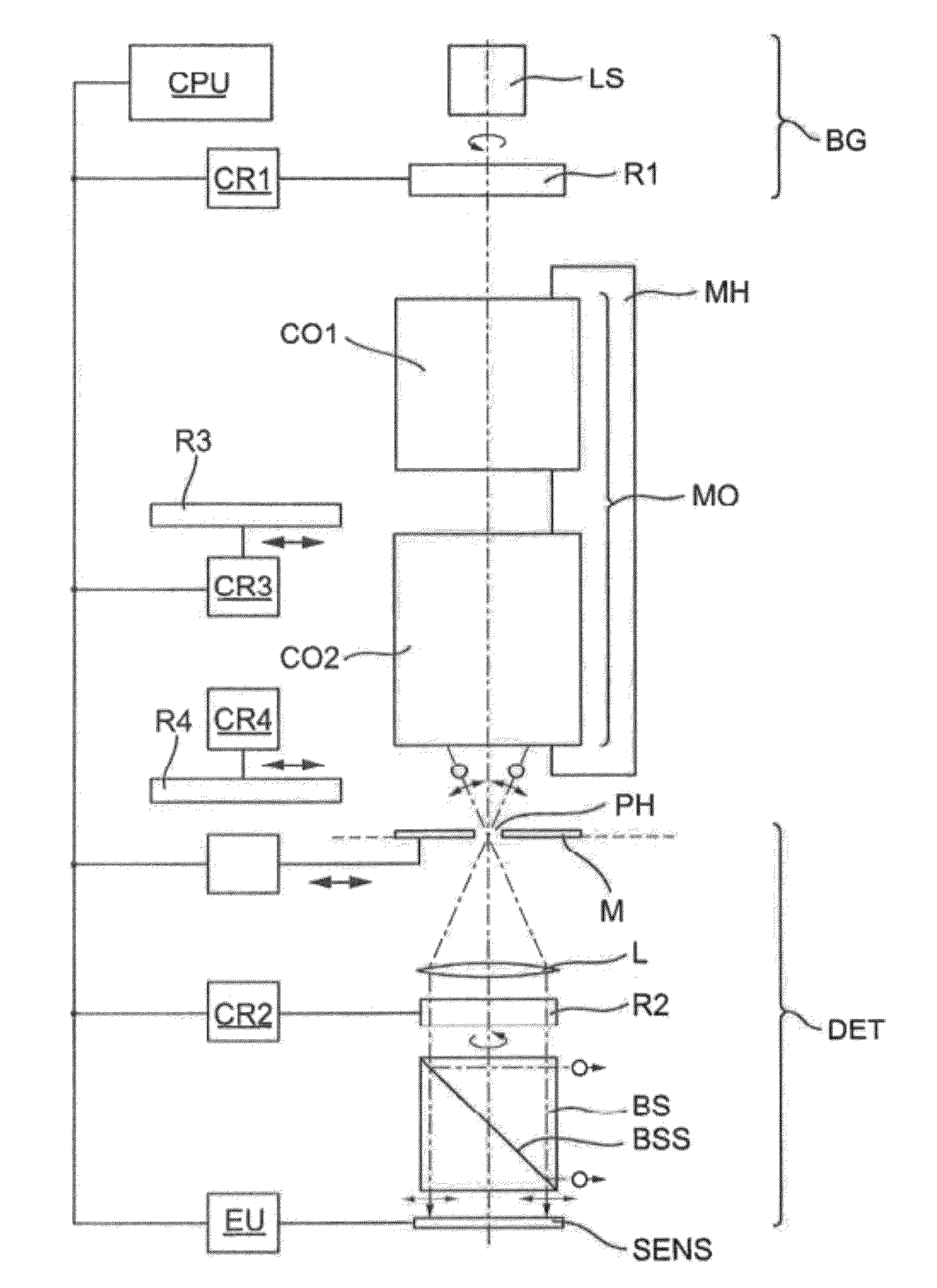
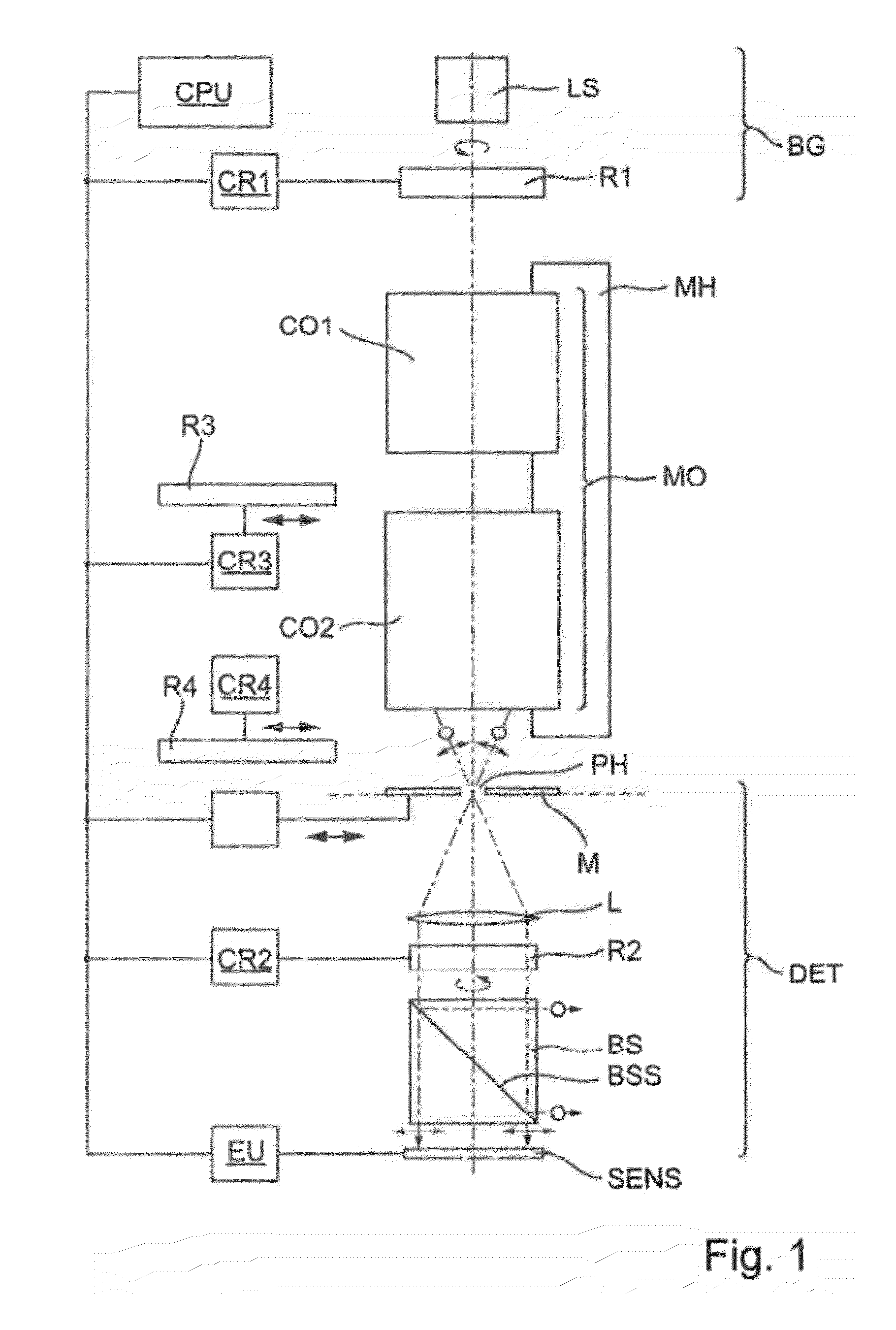
[0082]FIG. 1 shows an embodiment of a measurement system MS for measuring the birefringence of a measurement object MO, which in the case of the example is constructed in multipartite fashion and comprises a first component CO1 and also a second component CO2 arranged downstream thereof in the transmission direction, which are jointly held in a measurement object holding device MH in the manner in which they are also arranged relative to one another when an optical system containing the two components is used as intended. The measurement system comprises a beam generating unit BG for generating a measurement beam which is directed onto the measurement object and which is intended to have a defined input polarization state upon entering into the measurement object, and also a detector unit DET for detecting polarization properties of the measurement beam after passage through the measurement object or upon entry into the detector unit. If a measurement object is situated in the measu...


PUM

PropertyMeasurementUnit
wavelengthsaaaaaaaaaa

Abstract

A method measuring the birefringence of an object. A measurement beam having a defined input polarization state is generated, the measurement beam being directed onto the object. Polarization properties of the measurement beam after interaction with the object are detected in order to generate polarization measurement values representing an output polarization state of the measurement beam after interaction with the object. The input polarization state of the measurement beam is modulated into at least four different measurement states in accordance with a periodic modulation function of an angle parameter α, and the polarization measurement values associated with the at least four measurement states are processed to form a measurement function dependent on the angle parameter α. A two-wave portion of the measurement function is determined and analysed in order to derive at least one birefringence parameter describing the birefringence, preferably by double Fourier transformation of the measurement function.

Description

CROSS REFERENCE TO RELATED APPLICATIONS[0001]This application is a Continuation of International Application PCT / EP2010 / 001476, with an international filing date of Mar. 10, 2010, which was published under PCT Article 21(2) in English, which claims priority under 35 U.S.C. §119(a) to German Patent Application No 10 2009 015 393.4 filed on Mar. 20, 2009, and also to U.S. Provisional Patent Application 61 / 162,004 filed on Mar. 20, 2009. The entire contents of each of these three applications are incorporated into the present application by reference.BACKGROUND OF THE INVENTION[0002]1. Field of the Invention[0003]The invention relates to a measurement method for measuring the birefringence of an optical measurement object, and to a measurement system suitable for carrying out the measurement method.[0004]2. Description of the Related Prior Art[0005]In many gases, liquids and stress-free amorphous solids, for example optical glasses, the speed of light is independent of the direction of...

Claims


Application Information

Patent Timeline
Patent Type & Authority Applications(United States)
IPC IPC(8): G01N21/23G01J4/00
CPCG01M11/0257G03F7/70591G03F7/70566G01N21/23
Inventor FIOLKA, DAMIANROHE, MARC
Owner CARL ZEISS SMT GMBH
Why Eureka
Try Eureka