Electrical contact, electrophotographic photosensitive drum, and process cartridge

a technology of photosensitive drum and electrical connector, which is applied in the direction of electrographic process apparatus, instruments, optics, etc., can solve the problems of aforementioned conventional structural arrangement of electrical connection, difficult to provide an electrical connector for a photosensitive drum, and aforementioned problems, and achieve the effect of small diameter and stable contact pressur

Active Publication Date: 2012-04-19
CANON KK
View PDF4 Cites 2 Cited by
  • Summary
  • Abstract
  • Description
  • Claims
  • Application Information

AI Technical Summary

Benefits of technology

[0008]The present invention is one of the results of the improvement of an electrical connector such as those described above. Thus, the primary object of the, present invention is to provide an electrical connector for an electrophotographic photosensitive drum, which is stable in the contact pressure between itself and an external electrical connector, and yet, can be placed inside even the cylindrical member of an electrophotographic photosensitive member, which is significantly smaller in diameter than the cylindrical member of a conventional electrophotographic photosensitive drum.

Problems solved by technology

In recent years, however, this setup has become problematic because of the increase in the desire for a small electrophotographic image forming apparatus.
Thus, the aforementioned conventional structural arrangement for electrical connection has become problematic for the following reason.
That is, with the reduction in the diameter of the cylindrical member of a photosensitive drum, it became difficult to provide an electrical connector for a photosensitive drum, which is structured like the aforementioned conventional electrical connector, and yet, is placeable in a small place, unlikely to suffer from plastic deformation, and stable in electrical connection.

Method used


Image

  • Electrical contact, electrophotographic photosensitive drum, and process cartridge
  • Electrical contact, electrophotographic photosensitive drum, and process cartridge
  • Electrical contact, electrophotographic photosensitive drum, and process cartridge

Examples


embodiment 1

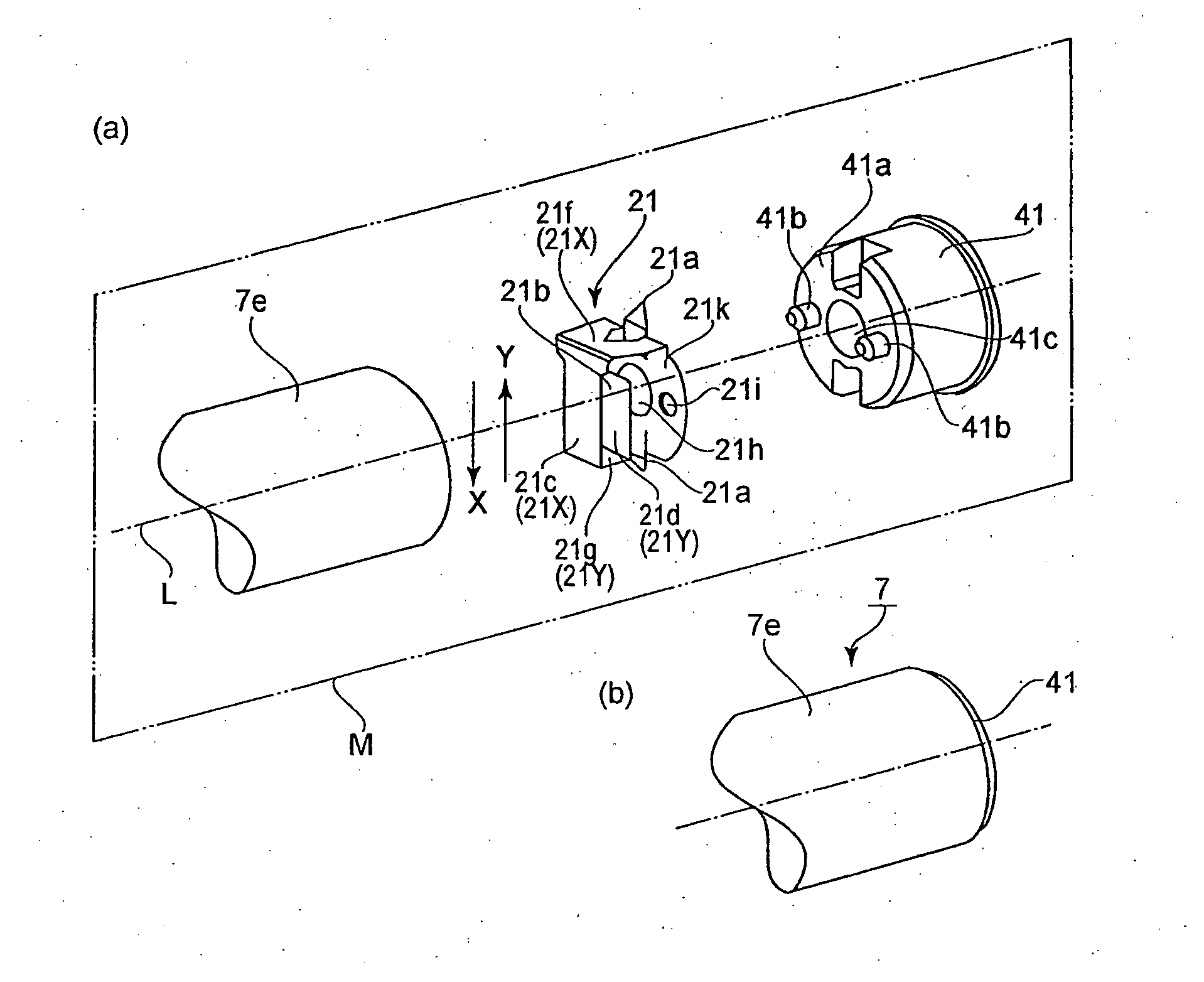
[0047]FIG. 5(a) is an exploded perspective view of the right end portion of the photosensitive drum 7, that is, the end portion having the electrical connector 21, in-the first preferred embodiment of the present invention. It shows the structure of the right end portion of the photosensitive drum 7. As is evident from FIG. 5(a), the photosensitive drum 7 comprises the cylindrical member 7e, an electrical connector 21, and a flange 41. The cylindrical member 7e is electrically conductive. Its peripheral-surface is covered with a photoconductive layer. The flange 41 is for immovably supporting the electrical connector 21 within the cylindrical member 21.

[0048]The electrical connector 21 is for keeping electrical connection between the cylindrical member 7e and the apparatus main assembly 100A. It has a pair of first portions of contact 21a and a pair of second portions of contact 21b. The first portion of contact 21a is the portion of the electrical connector 21, by which the connect...

embodiment 2

[0065]FIG. 7(a) is an exploded perspective view of the right end portion of the photosensitive drum 207 in the second preferred embodiment of the present invention. It shows the structure of the right end portion of the photosensitive drum 207, which has an electrical connector 22. FIG. 7(b) is a perspective view of the right end portion of the photosensitive drum 207. It shows the structure of the right end portion. The structural components of the photosensitive drum 207 in the second embodiment, which are the same in structure and effects as the counterparts in the first embodiment, are given the same referential codes as those given to the counterparts one for, one, and are not going to be described here. The cartridge and image forming apparatus to which the electrical connector 22 in the second embodiment is compatible are the same as the one in the first embodiment. Therefore, they are not going to be described here. The difference between the right end of the photosensitive ...

embodiment 3

[0068]FIG. 9(a) is a perspective view of the combination of the electrical connector 23, drum shaft 61, and flange 41 in the third preferred embodiment. It shows the structure of the combination. FIG. 9(b) is a plan view of the combination of the cylindrical member 7e (right end portion), electrical connector 23, and flange 41. It shows the structure of the combination. FIG. 9(c) is a sectional view of the cylindrical member 7e (right end portion), electrical connector 23, flange 41, and drum shaft 61, at the aforementioned plane M. It shows the structure of the combination. The structural components of the photosensitive drum 307 in the third embodiment, which are the same in structure and effects as the counterparts in the first and second embodiments are given the same referential codes as those given to the counterparts one for one, and are not going to be described here. The cartridge and image forming apparatus to which the electrical connector 22 in the third embodiment is co...


PUM


Abstract

An electrical contact member for electrically connecting to an external contact which is electrically connected with an electroconductive cylindrical member having a photosensitive layer on an outer surface thereof and which is provided outside the cylindrical member, the electrical contact member comprising a first contact portion contacted with the cylindrical member; a second contact portion contacted with the external contact; a first extension connected electrically with the first contact portion and extending in a diametrical direction across an axis of the cylindrical member; and a second extension electrically connecting with the first extension and extending the diametrical direction toward the axis, the second extension being provided with the second contact portion, wherein when second contact portion is contacted by the external contact, second contact portion displaces along the axis.

Description

FIELD OF THE INVENTION AND RELATED ART[0001]The present invention relates to an electrical connector, an electrophotographic photosensitive drum, and a process cartridge having an electrophotographic photosensitive drum.[0002]An electrophotographic image forming apparatus to which the present invention relates is an apparatus which forms an image on recording medium (ordinary paper, OHP sheet, and the like, for example) with the use of an electrophotographic image formation method. Examples of an electrophotographic image forming apparatus include an electrophotographic copying machine, an electrophotographic printer (laser beam printer, LED printer, and the like, for example), and a facsimile machine.[0003]A process cartridge to which the present invention relates is a cartridge in which an electrophotographic photosensitive drum, and at least one processing means, more specifically, a charging means, a developing means, or a cleaning means, are integrally contained, and which is r...

Claims


Application Information

Patent Timeline
Patent Type & Authority Applications(United States)
IPC IPC(8): G03G15/00
CPCG03G21/1867
Inventor KOISHI, ISAO
Owner CANON KK
Why Eureka
Try Eureka