Blade Orientation of an Impeller or Propeller

Inactive Publication Date: 2012-04-19
SMITH MIKE RICHARD JOHN
View PDF4 Cites 2 Cited by
  • Summary
  • Abstract
  • Description
  • Claims
  • Application Information

AI Technical Summary

Benefits of technology

[0004]It is therefore the object of the present invention to provide a more efficient impeller by orienting the blade lines angles of the radial sections of at least one blade or more blade

Problems solved by technology

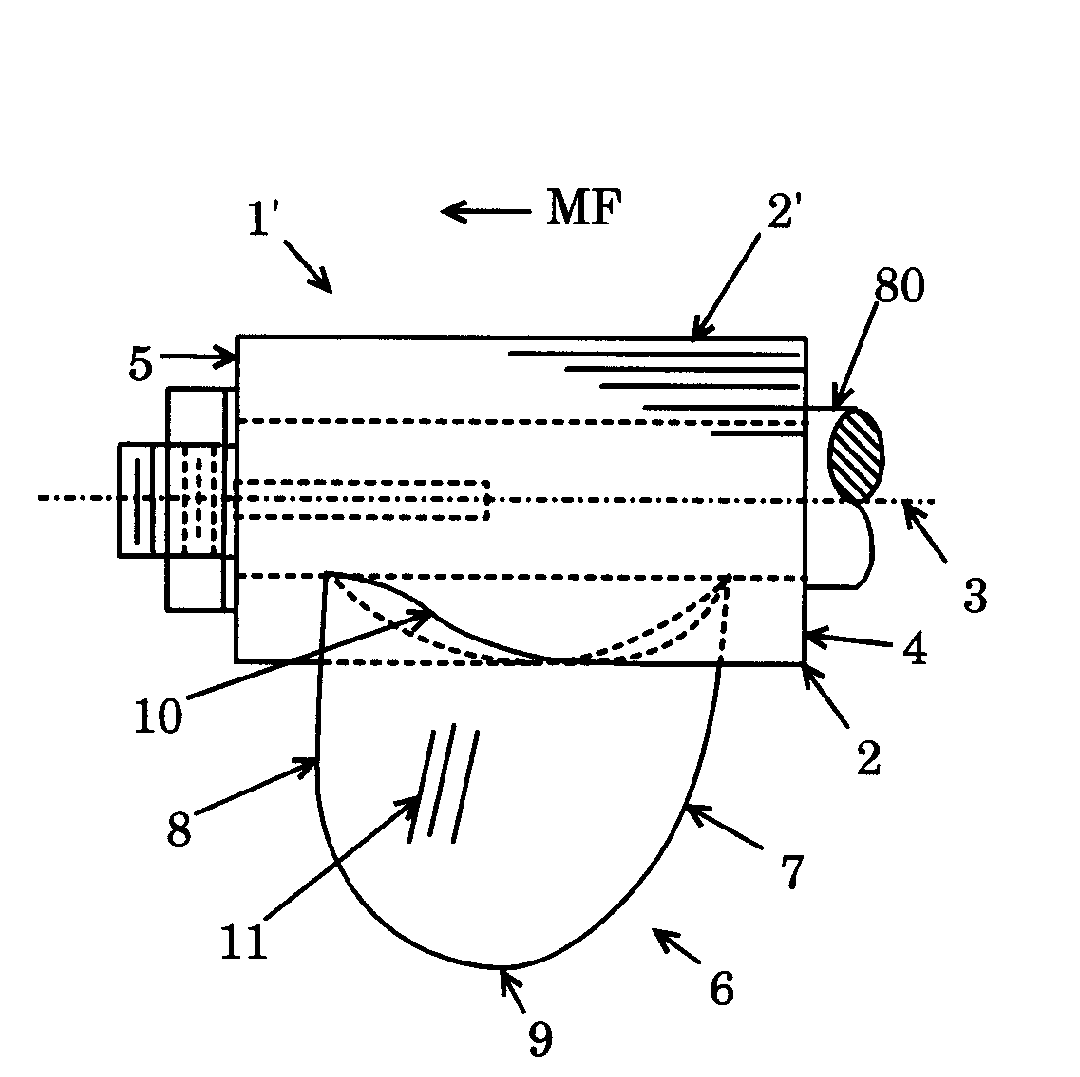
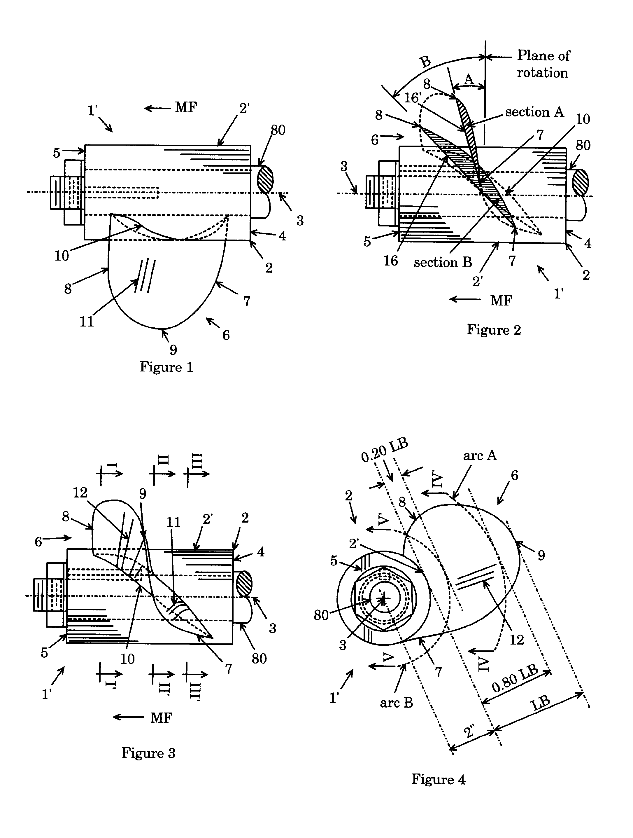
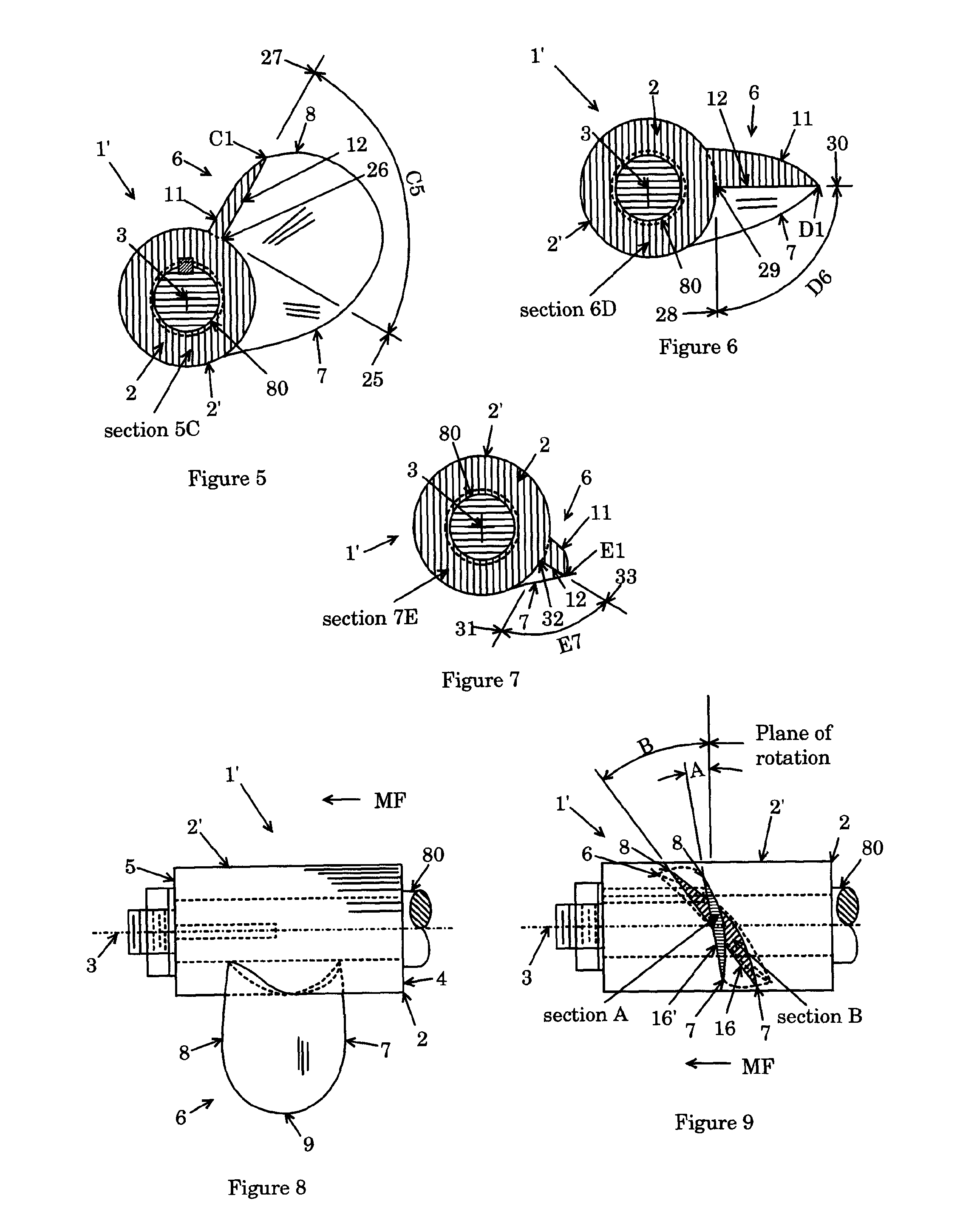
The movement of the medium or fluid to the side which is caused by the blade is evident to those skilled in the art by viewing the screw type impeller from the side while slowly rotating the said impeller on the longitudinal axis, large area of the blade working face is visible which means portion of the impeller rotational energy is used by the blade in pushing the fluid or medium sideways which is quite inefficient since moving the medium or fluid sideways does not move the impeller forward but surely makes the medium or fluid turbulent.
Force Fx therefore decreases the value of force Fy and force Fz thus making the old system with less usable power for the forward propulsion which proves the prior art impeller is a relatively inefficient device.
The prior art impeller used in hydro-electric turbines and wind turbines is inefficient too since the prior art blade orientation systematically makes the working medium or fluid force on the blade high pressure face to push the blades, hub, and shaft so much which causes more friction and slows down the rotation of the hub as opposed to utilizing the force for rotating the hub or impeller.
The said larger frontal area of the prior art impeller is less efficient since the blade with distinctive twist encounters more resistance or drag when the prior art impeller is rotated on the longitudinal axis of the said impeller for forward motion when used in a motor driven system or when the said impeller is rotated in medium or fluid driven system.
In mixing or agitator systems the said distinctive blade twist moves the material in a multi-directional way which slows down the circulation of the medium, so the prior art impeller in an agitator plants or mixing plants is less e

Method used


Image

  • Blade Orientation of an Impeller or Propeller
  • Blade Orientation of an Impeller or Propeller
  • Blade Orientation of an Impeller or Propeller

Examples


Example

[0120]FIG. 69 and FIG. 69A shows the second embodiment of the present invention wherein the present invention impeller 1 is a multi-set configuration impeller wherein the blades are oriented in accordance to the present invention. FIG. 69 shows the side elevation view of the impeller wherein one blade 6 of the preceding set 19 and one blade 6 of the next set 20 are shown wherein the tilted plane 13 angle TA of at least one blade 6 of the preceding set 19 and the tilted plane 13 angle TA of the next set 20 is substantially the same and wherein the high pressure face 12 area of the said one blade 6 of said preceding set 19 and the high pressure face 12 area of the said one blade 6 of said next set 19 are substantially the same. FIG. 69A is the section view of the blade 6 on line IX-IX′ of the impeller in FIG. 69 and also the section view on line X-X′ of the impeller in FIG. 69. In FIG. 69A shows the blade 6(19, 20) in the preceding set 19 and in the next set 20 with the same high pres...

Example

[0123]FIG. 72 and FIG. 72A illustrates the third embodiment of the present invention wherein the present invention impeller 1 with multi-set configuration with blades oriented in accordance to the present invention. FIG. 72 is the side elevation view of the present invention impeller 1 with two set of blade 6 on the hub 2 as shown namely, the preceding set 19 and the next set 29 wherein the tilted plane 13 angle TA of at least one blade 6 in the preceding set 19 is greater than the tilted plane 13 angle TA of at least one blade 6 in the next set 20 and wherein the high pressure face 12 area of the said one blade 6 in the said next set 20 is between one percent to fifty percent less the high pressure face 12 area of the said one blade 6 in the said preceding set 20. FIG. 72A is the second end 5 view of the present invention impeller 1 in FIG. 72. FIG. 72A shows the location line P(19, 20) of the blade 6 in the preceding set 19 and in the next set 20 from the second vertical plane 14′...

Example

[0126]FIG. 75 and FIG. 75A shows the fourth embodiment of the present invention wherein the present invention impeller 1 is a multi-set configuration impeller. FIG. 75 is the side elevation view of the present invention impeller 1 with two set of blades which are non-intrusive configuration with at least one blade 6 of the preceding set 19 has less high pressure 12 area than the high pressure face 12 area of at least one blade 6 in the next set 20 and wherein the tilted plane 13 angle TA of a blade 6 in the preceding set 19 is substantially the same as the tilted plane 13 angle TA of at least one blade 6 in the next set 20. FIG. 75A is the second end 5 view of the impeller shown in FIG. 75. In FIG. 75A shows the angle of location line P(19) of the blade 6 in the preceding set 19 is greater than the location line P(20) angle of the blade 6 in the next set 20 but the location line P(19) angle of the blade 6 in the preceding set 19 maybe modified to a less angle or the same angle as th...


PUM


Abstract

Efficient impeller or propeller wherein at least one blade in a set of blades on a hub of said impeller is oriented with respect to the tilted plane rotated clockwise or counter clockwise in an axis perpendicular to the longitudinal axis of said impeller. At least one blade in a set of blades of the multi-set impeller may have the same or different sizes or the same or different tilted plane angle compared to at least one blade of the adjacent set or the blade of one set may have the same or different angle as viewed from the second end of the impeller from a reference plane along the longitudinal axis of the impeller compared to the angle of at least one blade of the adjacent set. The invention also includes: blade arrangement for multi-set impeller, inner hub length variations, and hub shapes for better efficiency and utility.

Description

BACKGROUND OF THE INVENTION[0001]The present invention relates to a more efficient impeller or propeller and impeller or propeller related systems for: watercrafts, weapon systems, air vehicles, drones, hydro-electric plants, pumps, mixing and agitation plants, compressors, and wind farms.[0002]The prior art impeller for: watercrafts, weapon systems, air vehicles, drones, pumps, agitation systems or mixing plants, hydro-electric plants, compressors, and wind farms are not so efficient because each blade in the set of blades has blade lines with (in the present invention the blade line is a straight line that connects the leading edge and the trailing edge of an specific radial section of a blade) acute angles measured perpendicularly from the plane of rotation intersecting the blade base which is similar to the blade lines acute angles of the blade radial sections of the screw type impeller. The screw type impeller blade on the hub is constructed on the principle of the Archimedes' ...

Claims


Application Information

Patent Timeline
IPC IPC(8): F01D5/00
CPCB63H1/26F03B3/121F03D1/0608Y02E10/721F04D29/384Y02E10/223F04D29/181F05D2250/70Y02E10/20Y02E10/72
Inventor SMITH, MIKE RICHARD JOHN
Owner SMITH MIKE RICHARD JOHN
Why Eureka
Try Eureka