Impeller and propeller

a technology of impeller and propeller, which is applied in the direction of liquid fuel engines, marine propulsion, vessels, etc., can solve the problems of huge impact on operation profitability, and achieve the effect of facilitating a gradual acceleration of media, efficient impellers, and efficient impellers

Inactive Publication Date: 2004-02-10
KEETON JOHN P
View PDF4 Cites 4 Cited by
  • Summary
  • Abstract
  • Description
  • Claims
  • Application Information

AI Technical Summary

Benefits of technology

It is an object of this invention to disclose multiple variations in the design of an impeller which individually result in a more efficient impeller. In combination, these variations result in a substantially more efficient impeller. It is an object of this invention to disclose an impeller which has substantially varying slopes which increase from the leading, to the trailing edge of the impeller, and which facilitate a gradual acceleration of the media when the impeller rotates. It is an object of this invention to disclose an impeller which is designed to efficiently penetrate the media as it rotates. The peripheral portion of the spiralled leading edge of the impeller comprises a bulbuous tip which is the first portion of the blade to penetrate the media. This bulbuous tip is fashioned after a bulbuous bow on a ship. It is yet a further object of this invention to disclose an impeller design which is shaped to inwardly accelerate the media as it rotates therein. A blade portion of the impeller increases in slope from its inner to its peripheral edge. The impeller effectively draws the media to its central portion wherein the media is trapped and accelerated parallel to the axis of the impeller. The resulting wake produced by an operating impeller is generally more axially directed than an impeller of conventional design which throws the media more outwardly and whose wake tends to be more outwardly directed. It is a final object of this invention to disclose an impeller having a leading edge which spirals back from the extended bulbuous tip to the central hub thereof.
In an impeller for rotation in a media of the type having a central hub, an inclined blade portion having an inner radial edge portion attached to the central hub, an intermediate blade portion adjoined to the inner radial edge portion on one side, a peripheral edge portion attached to and extending outwardly from the central portion, a leading edge portion, a trailing edge portion, a front face, and a rear face, one aspect of this invention provides for an impeller having the following improvement. The blade portion has a front media-accelerating face and substantially varying slopes which increase from the leading to the trailing edge portions of the media-accelerating front face of the impeller, to facilitate a gradual acceleration of the media as the impeller rotates. The slope of front media-accelerating face of the blade portion also gradually increases moving outwardly along the intermediate blade portion, then to and along the peripheral edge portion thereof. The blade portions have increasing slope to accelerate the media more axially, and less radially, as the impeller rotates.

Problems solved by technology

Many of the variations which he has produced have an empirical appeal as sensible, but none the less, these variations are radical in industries which have been relatively static in impeller designs for long periods.
Operational profitability is hugely impacted.

Method used


Image

  • Impeller and propeller
  • Impeller and propeller
  • Impeller and propeller

Examples


Embodiment Construction

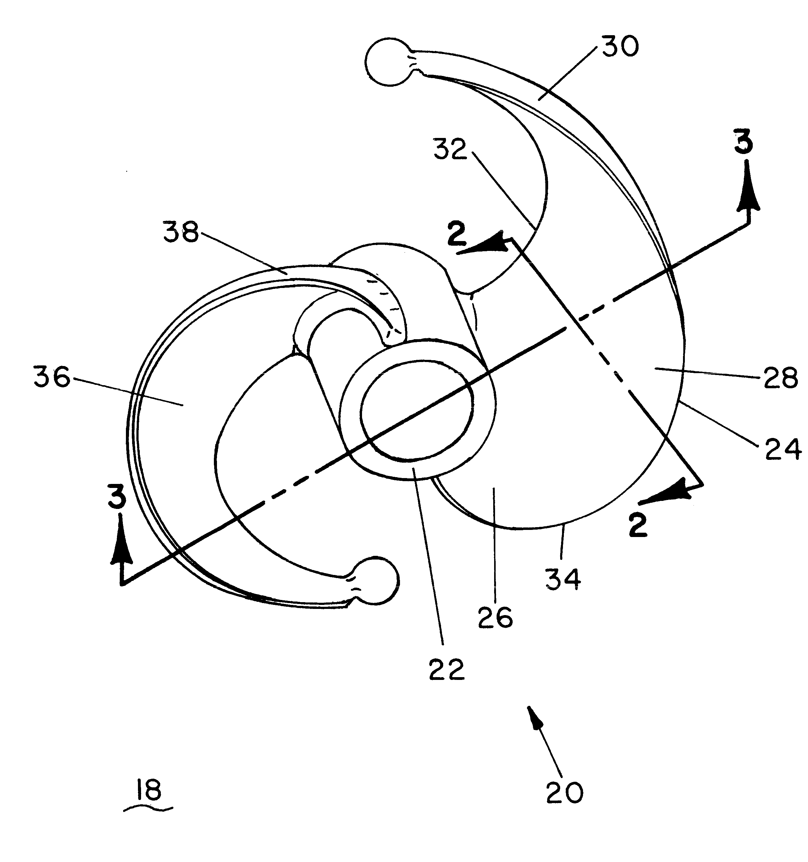
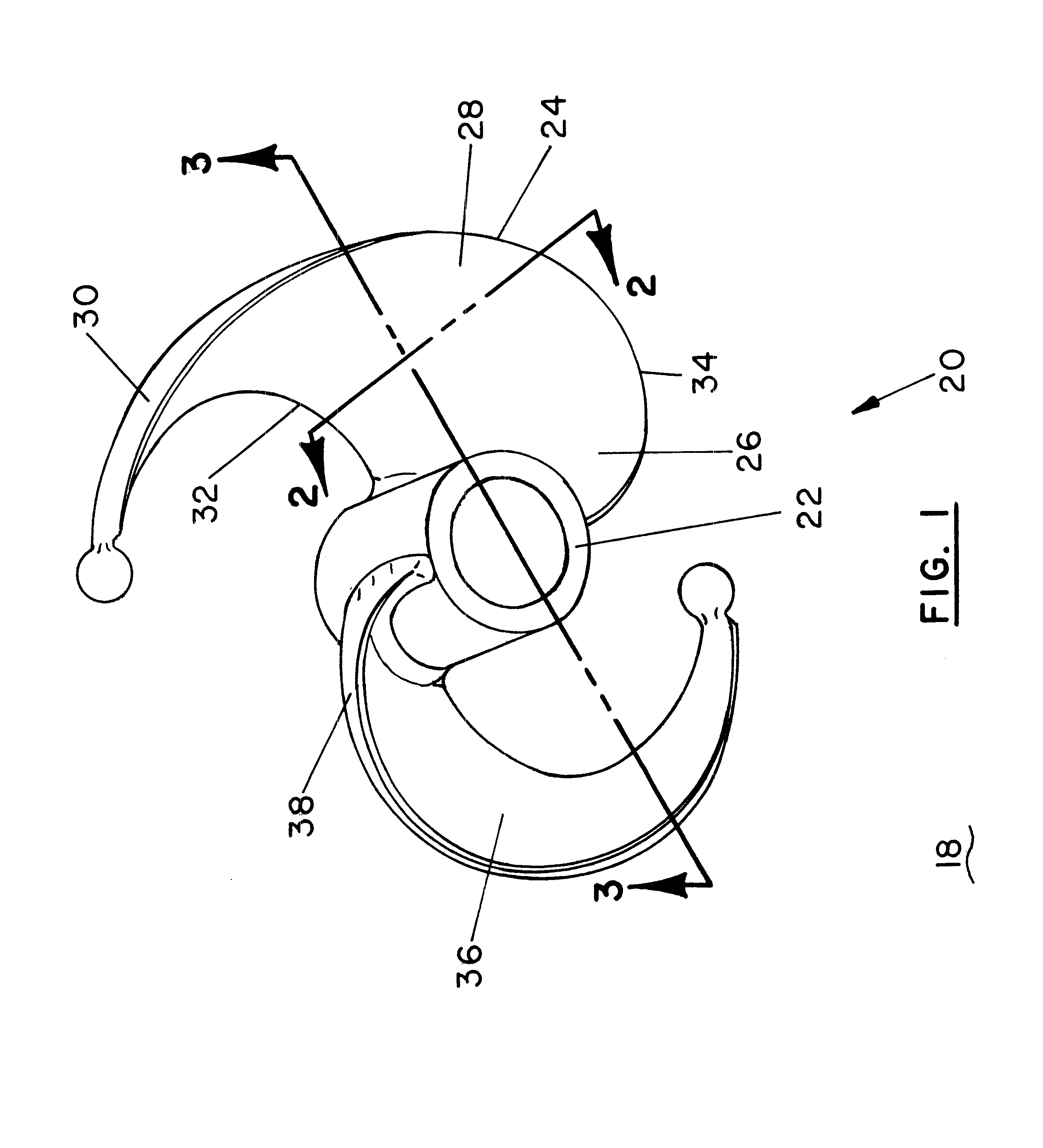
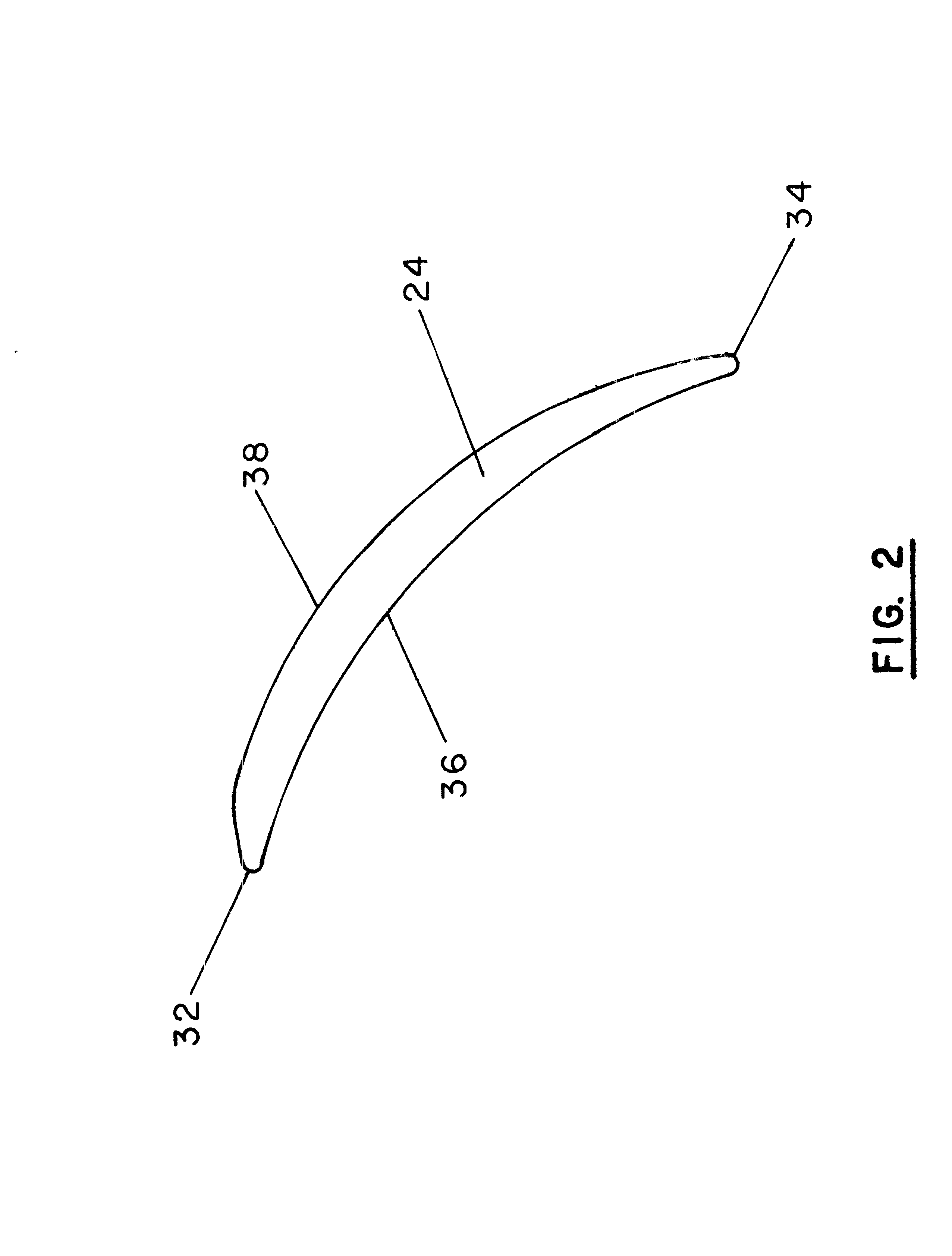
Turning now to the drawings and,more particularly to FIG. 1 we have a perspective view of an improved impeller 20. Within this application and the claims thereof, impeller is defined to include a propeller. The impeller 20, for rotation in a media 18, is of the type having a central hub 22, an inclined blade portion 24 having an inner radial edge portion 26 attached to the central hub 22, an intermediate blade portion 28 adjoined to the inner radial edge portion 26 on one side, a peripheral edge portion 30 attached to and extending outwardly from the central portion 28, a leading edge portion 32, a trailing edge portion 34, a front media-accelerating face 36, and a rear face 38. The improvement, not found in a conventional impeller 20 comprises the blade portion 24 having a media-accelerating front face 36 and substantially varying slopes which increase from the leading edge portion 32 to the trailing edge portion 34 of the media-accelerating front face 36 of the impeller 20. Accord...


PUM


Abstract

An improved impeller which facilitates greater linear movement of a media with less torque; and which accordingly, consumes less power. A blade portion of the impeller has a front media accelerating face and substantially varying slopes which increase from the leading to the trailing edge portions of a media-accelerating front face thereof, to facilitate a gradual acceleration of the media as the impeller rotates. The slope of the front face of the blade portion also gradually increases moving outwardly along the intermediate blade portion, from the hub to the peripheral edge portion thereof. The blade portions have increasing slope to accelerate the media more axially, and less radially, as the impeller rotates. The leading and trailing edge portions of the blade portion each have an elongated forwardly extended peripheral portion, which culminates in a tip portion, which is most preferably bulbuous, to facilitate efficient penetration of the media by the blade portion.

Description

This invention relates to impellers and agitors used to mix industrial slurries and also used to propel marine vessels. More particularly this invention relates to an impeller having a unique design which facilitates greater linear movement of a media with less torque; and which accordingly, consumes less power, to perform equivalent work.The applicant is a mechanical designer who has worked and experimented with impellers used in mixing. He has extensively varied impeller parameters which are commonly accepted in hopes of producing a more efficient impeller. Many of the variations which he has produced have an empirical appeal as sensible, but none the less, these variations are radical in industries which have been relatively static in impeller designs for long periods.Efficiency and energy conservation today more than ever are principal concerns, and almost the only concern in the design of impellers for use in any media.One accepted measure of an impeller's efficiency is the rat...

Claims


Application Information

Patent Timeline
Patent Type & Authority Patents(United States)
IPC IPC(8): B01F15/00B63H1/26B63H1/00F04D29/18B01F7/00
CPCB01F7/00341B63H1/26F04D29/183B01F27/113
Inventor KEETON, JOHN P.
Owner KEETON JOHN P
Why Eureka
Try Eureka