
Through-the-earth radio

Inactive Publication Date: 2006-05-09
LOS ALAMOS NATIONAL SECURITY
View PDF10 Cites 36 Cited by
  • Summary
  • Abstract
  • Description
  • Claims
  • Application Information

AI Technical Summary

Benefits of technology

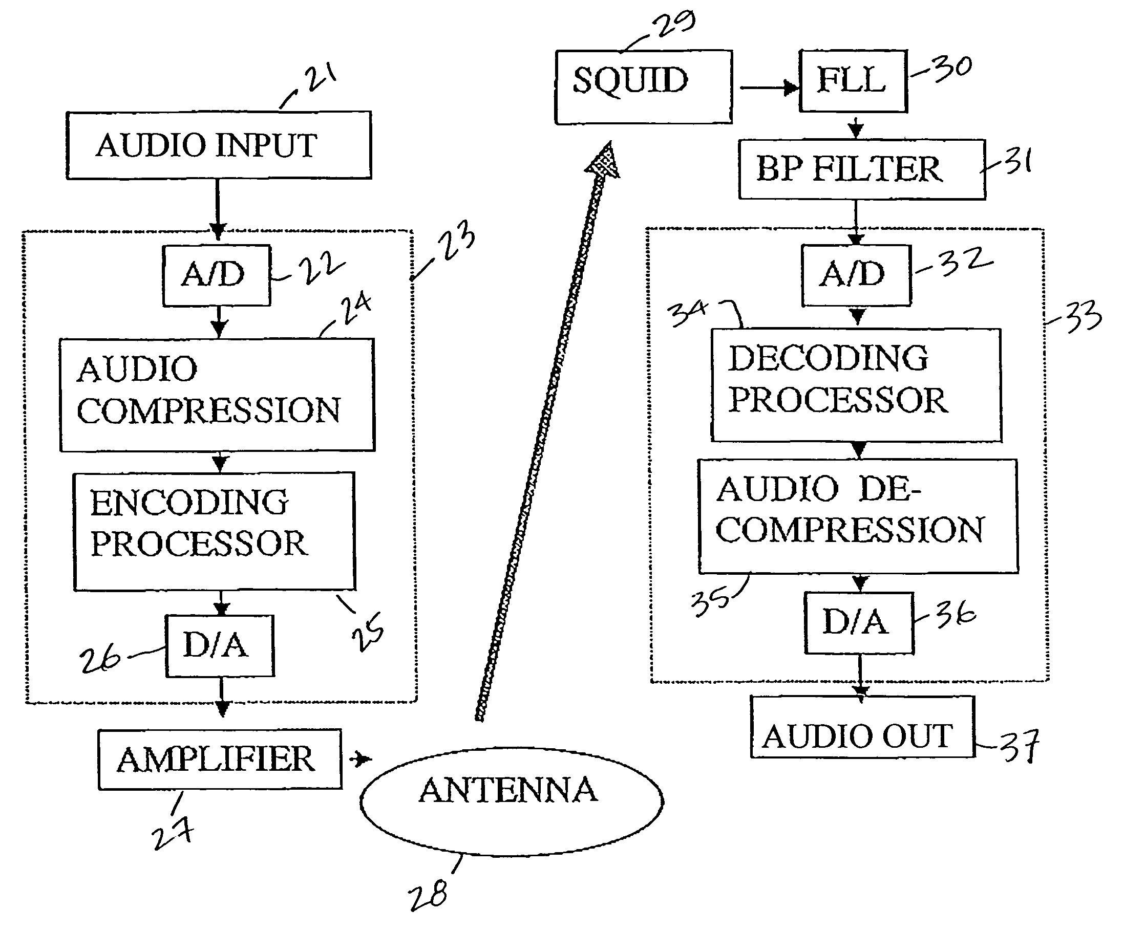
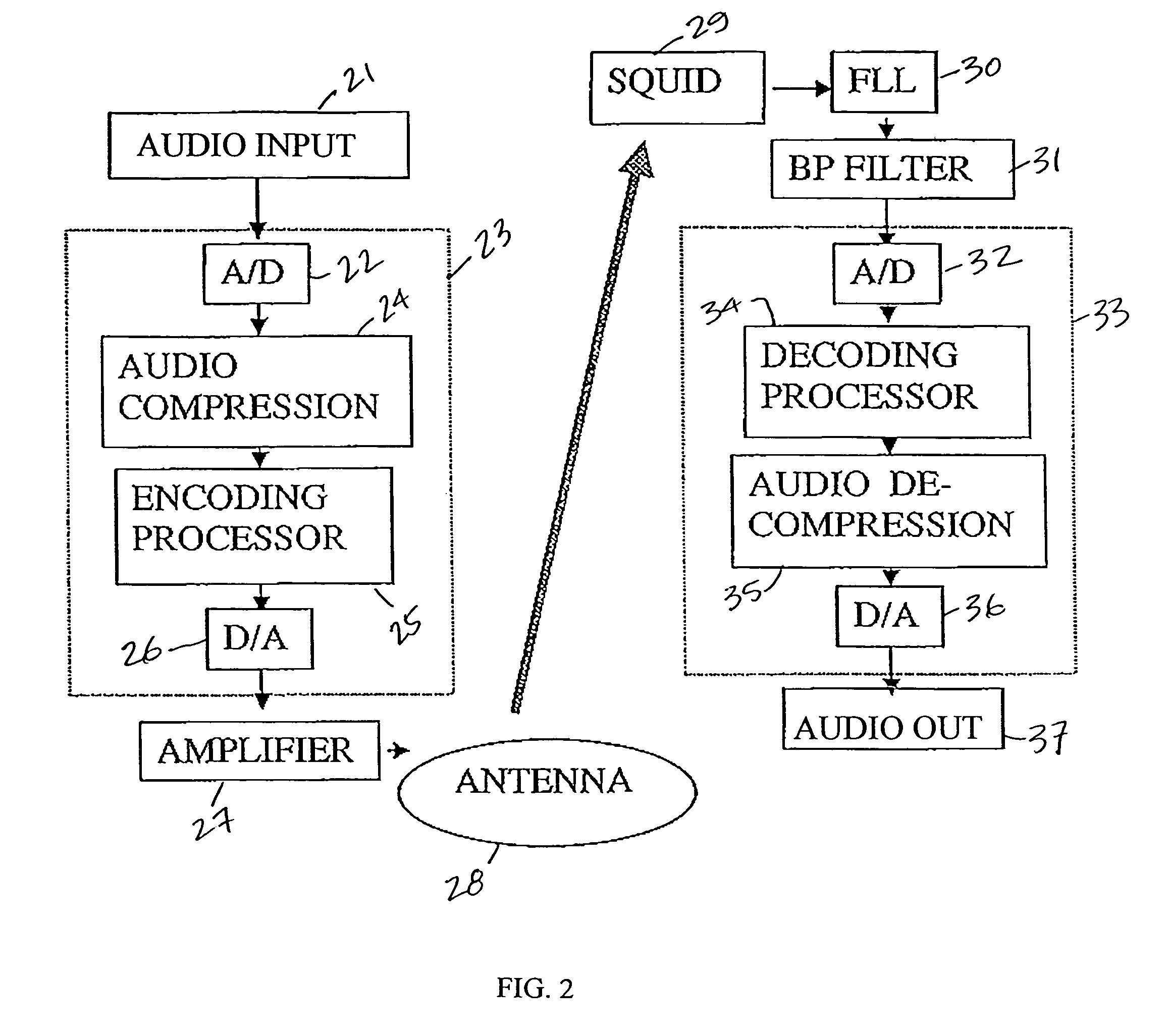
[0019]In a still further aspect of the present invention and in accordance with its principles and objectives, a method of conducting through-the-earth communication comprises the steps of inputting an analog signal; digitizing the analog signal; compressing the digitized signal; encoding the compressed digitized signal to encode a predetermined data stream into the compressed digitized signal; and outputting the encoded compressed digitized signal through an antenna at a predetermined frequency that is sufficiently low to effectively penetrate useful distances through-the-earth as a transmitted signal; receiving the transmitted signal with an antenna after the transmitted signal has propagated through-the-earth; converting the transmitted signal from an analog signal to a digital signal: decoding the digital signal; decompressing the digital signal; and outputting the decoded decompressed digital signal.

Problems solved by technology

In the past, such communications were problematic and often ineffective.
While phone lines between fixed points provide some measure of communication, these fixed locations may be difficult or impossible to reach in emergency situations.
Thus, direct radio communication with underground positions has proven extremely difficult.
This method suffers from limited range, and is easily interrupted by damage to the cables.
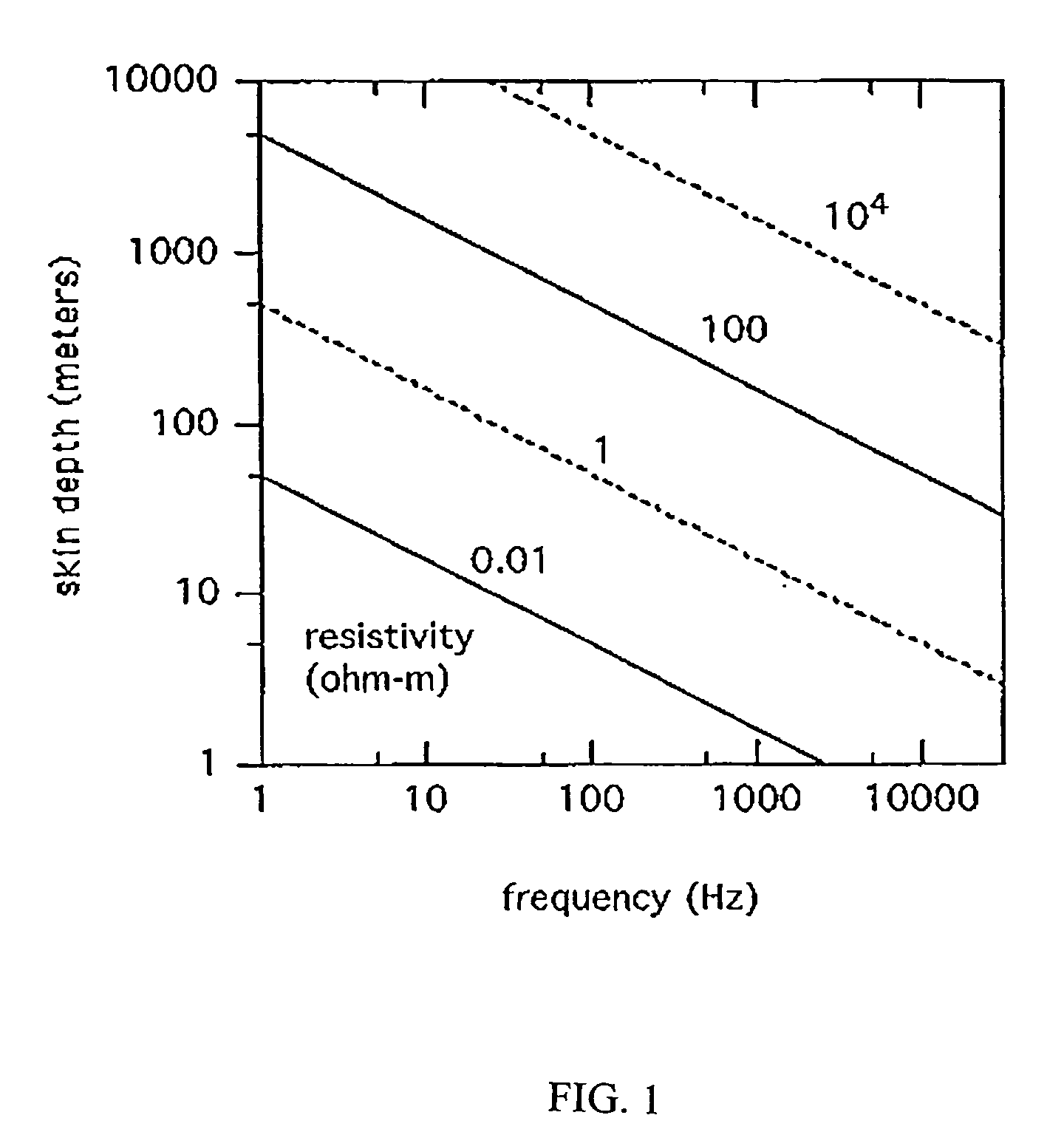
Evaluating the skin depth for actual geologies is not straightforward because the resistivity is quite variable.
Conventional radio transmissions use frequencies higher than 500 kHz, but these higher frequencies are weakly ground penetrating.
High temperature superconducting receivers are not expected to have noise floors below 1 fT / √Hz in the foreseeable future.
The dominant source of noise in a developed underground environment above the noise floor is the power line noise introduced by operations at the site.
This results in the locking of the SQUID to the operating point of a specific flux.
Actually, the lower cryogenic requirements of HTS allow large cost and power savings over LTS.
This bandwidth is insufficient to carry the analog audio.
For voice audio alone, the bit rate can be reduced to 64,000 bits / sec, but this is still too high for a carrier signal of a few kilohertz.
Audio also has been transmitted successfully on an axis perpendicular to the plane of the antenna, the most difficult direction to send signals.

Method used


Image

  • Through-the-earth radio
  • Through-the-earth radio
  • Through-the-earth radio

Examples


Embodiment Construction

[0029]The present invention provides audio communication deep into underground locations. The invention can most easily be understood through reference to the drawings.

[0030]Referring first to FIG. 2, where a block diagram of the present invention is shown. Audio to be transmitted is input to audio input 21 and sent to analog to digital (A / D) converter 22 on board 23. Audio input 21 may be any desired audio input device, including a conventional microphone. Audio input 21 can be configured to accept input from remotely located walkie-talkies or other personal communication devices. Board 23 contains all the components for both transmitting and receiving. However, in FIG. 2, board 23 is configured to transmit. As shown A / D converter 22 provides its signal to audio compression 24, where it is compressed, and sent to encoding processor 25. Encoding processor 25 uses quadrature phase shift keying (QPSK), which is a technique that uses a constant amplitude signal with a 90° phase shift t...


PUM


Abstract

A method and apparatus for effective through-the-earth communication involves a signal input device connected to a transmitter operating at a predetermined frequency sufficiently low to effectively penetrate useful distances through-the earth, and having an analog to digital converter receiving the signal input and passing the signal input to a data compression circuit that is connected to an encoding processor, the encoding processor output being provided to a digital to analog converter. An amplifier receives the analog output from the digital to analog converter for amplifying said analog output and outputting said analog output to an antenna. A receiver having an antenna receives the analog output passes the analog signal to a band pass filter whose output is connected to an analog to digital converter that provides a digital signal to a decoding processor whose output is connected to an data decompressor, the data decompressor providing a decompressed digital signal to a digital to analog converter. An audio output device receives the analog output form the digital to analog converter for producing audible output.

Description

RELATED APPLICATIONS[0001]This application claims the benefit of provisional application No. 60 / 483,146 filed on Jun. 26, 2003, titled “Underground Radio”.[0002]The present invention generally relates to radio communications and, more specifically relates to communication through-the-earth to or from an underground position. This invention was made with Government support under Contract No. W-7405-ENG-36 awarded by the U.S. Department of Energy. The Government has certain rights in the invention.BACKGROUND OF THE INVENTION[0003]Anytime personnel or equipment are located underground, such as in mines, tunnels or boreholes, a need exists for communication through-the-earth. In the past, such communications were problematic and often ineffective. While phone lines between fixed points provide some measure of communication, these fixed locations may be difficult or impossible to reach in emergency situations. Additionally, even in normal conditions, mobile communications are necessary t...

Claims


Application Information

Patent Timeline
IPC IPC(8): H04B13/02
CPCH04B13/02
Inventor REAGOR, DAVIDVASQUEZ-DOMINGUEZ, JOSE
Owner LOS ALAMOS NATIONAL SECURITY
Learn More