Gas pressure-reducing valve

a gas pressure reduction and valve body technology, applied in the direction of fluid pressure control, process and machine control, instruments, etc., can solve the problems of reducing machining precision, gas pressure of the pressure-reducing chamber might fall large amount below the target control pressure,

Inactive Publication Date: 2002-07-04
KEIHIN CORP
View PDF0 Cites 29 Cited by
  • Summary
  • Abstract
  • Description
  • Claims
  • Application Information

AI Technical Summary

Problems solved by technology

In the above-mentioned conventional arrangement, since a pressure-reducing chamber is formed between one surface of the diaphragm and the body, the body structure surrounding the pressure-reducing chamber becomes complicated, thereby raising the possibility that the machining precision might be degraded.
Furthermore, when the diameter of the diaphragm is made small in order to satisfy a need for red...

Method used


Image

  • Gas pressure-reducing valve
  • Gas pressure-reducing valve
  • Gas pressure-reducing valve

Examples


Embodiment Construction

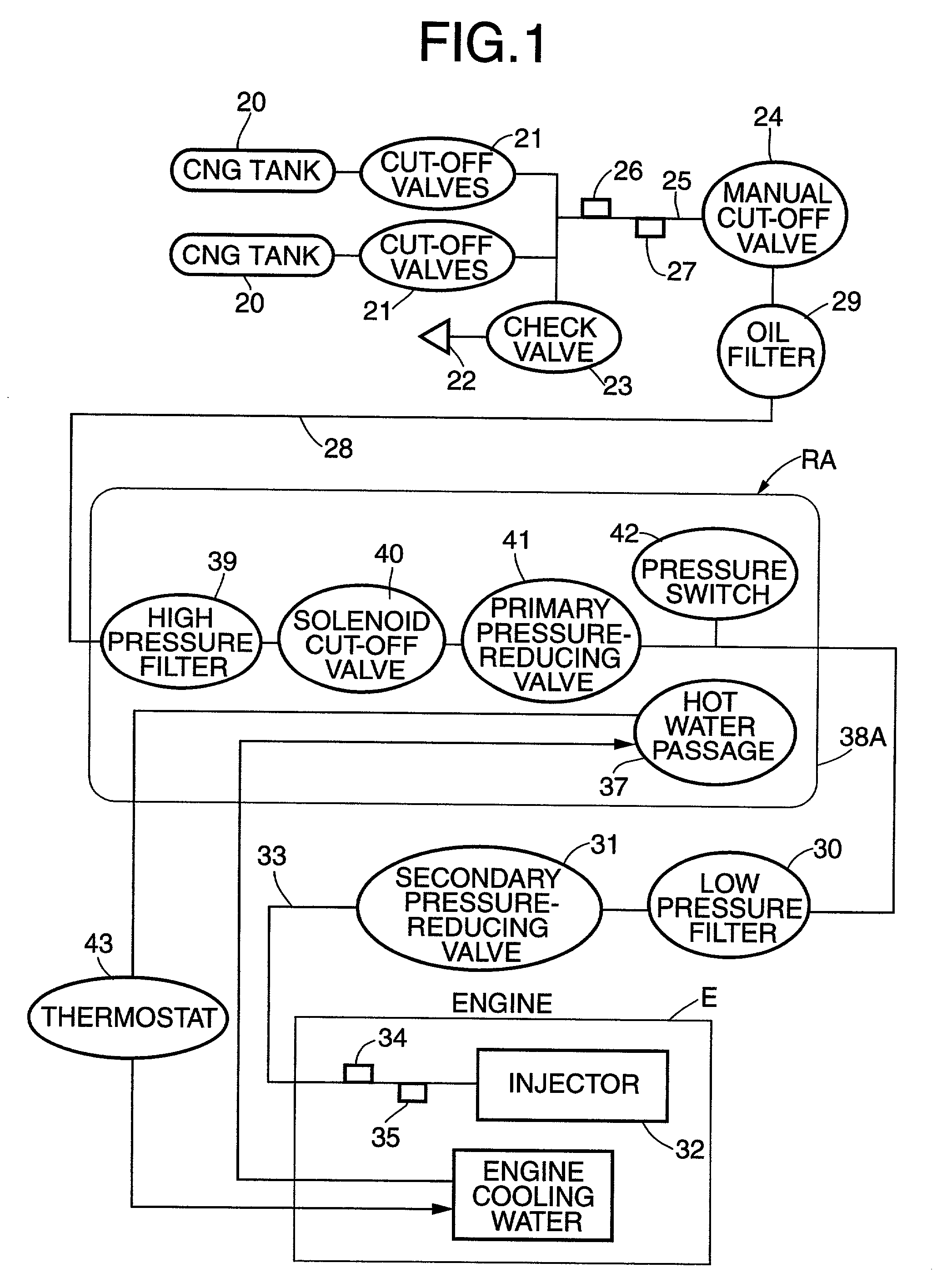
[0046] The first embodiment of the present invention is explained below by reference to FIGS. 1 to 22. Referring to FIG. 1, compressed natural gas (hereinafter called CNG), which is a gaseous fuel, is stored in one or a plurality of CNG tanks 20 at high pressure, for example, 25 to 1 MPa. The CNG tanks 20 are equipped with corresponding container cut-off valves 21 that are connected in common both to a filling inlet 22 via a check valve 23, and to a manual cut-off valve 24. A pressure sensor 26 and a temperature sensor 27 are attached to a pipeline 25 between the container cut-off valves 21 and the manual cut-off valve 24.

[0047] When the container cut-off valves 21 and the manual cut-off valve 24 are open, CNG from the CNG tanks 20 is guided to a regulator RA via a high pressure pipeline 28 equipped with an oil filter 29 for removing oil that might have contaminated the CNG when the CNG tanks 20 were filled with CNG by a compressor. The pressure of the CNG is reduced to, for example...


PUM


Abstract

A gas pressure-reducing valve includes a pressure-reducing chamber for generating a gas pressure that acts on one surface of a diaphragm, a valve body that can sit on a valve seat having in its central part a valve hole communicating with the pressure-reducing chamber, and a spring biasing the diaphragm in a direction that detaches the valve body from the valve seat. A valve housing is formed by conjoining a body, a partition, and a cover. The partition forms the pressure-reducing chamber between itself and the body and forms a pressure action chamber between itself and the diaphragm. The cover forms the spring chamber between itself and the other surface of the diaphragm and has the peripheral edge of the diaphragm clamped between itself and the partition. The partition has a through hole for allowing the valve stem to run through in an airtight and axially slidable manner and a communicating hole for providing communication between the pressure action chamber and the pressure-reducing chamber. The structure of the body can thus be simplified thereby enhancing the machining precision, and the diameter of the pressure-reducing chamber can be determined regardless of the diameter of the diaphragm.

Description

[0001] 1. Field of the Invention[0002] The present invention relates to a gas pressure-reducing valve. In particular, it relates to an improvement of a gas pressure-reducing valve, wherein a pressure-reducing chamber for generating a gas pressure that acts on one surface of a diaphragm is formed within a valve housing that clamps the peripheral edge of the diaphragm, a valve body that can sit on a valve seat having in its central part a valve hole communicating with the pressure-reducing chamber is fixed to one end of a valve stem penetrating the valve hole in an axially movable manner, the other end thereof being connected to the central part of the diaphragm, and a spring biasing the diaphragm in a direction that detaches the valve body from the valve seat is housed in a spring chamber formed within the valve housing, the spring chamber facing the other surface of the diaphragm.[0003] 2. Description of the Related Art[0004] Conventionally, such a gas pressure-reducing valve is alr...

Claims


Application Information

Patent Timeline
IPC IPC(8): G05D16/06
CPCG05D16/0663Y02T10/32F02M21/0239F02M21/0233Y02T10/30Y10T137/7793Y10T137/7801Y10T137/782Y10T137/7825
Inventor NAKAJIMA, YOUJIISHIKAWA, KAZUKISATO, YOSHIO
Owner KEIHIN CORP
Why Eureka
Try Eureka