Impeller blade with asymmetric thickness

a technology of asymmetric thickness and impeller blade, which is applied in the direction of non-positive displacement fluid engine, pump components, liquid fuel engine components, etc., can solve the problems of reducing the energy reducing the efficiency of the pump, and not specifically addressing the design of the blade for optimal performance in a variety of different flow conditions. , to achieve the effect of reducing the energy consumption of the pump, and reducing the energy consumption

Inactive Publication Date: 2018-08-02
IHC HOLLAND NV
View PDF3 Cites 3 Cited by
  • Summary
  • Abstract
  • Description
  • Claims
  • Application Information

AI Technical Summary

Benefits of technology

[0007]Such a blade with an asymmetric thickness, and being thicker on the suction side, results in a profile more resistant to flow sepa...

Problems solved by technology

While these blades are all designed to avoid problems under certain conditions (solids attaching to the blade or withstanding conditions and pressures that could damage the blade), none specif...

Method used


Image

  • Impeller blade with asymmetric thickness
  • Impeller blade with asymmetric thickness
  • Impeller blade with asymmetric thickness

Examples


Embodiment Construction

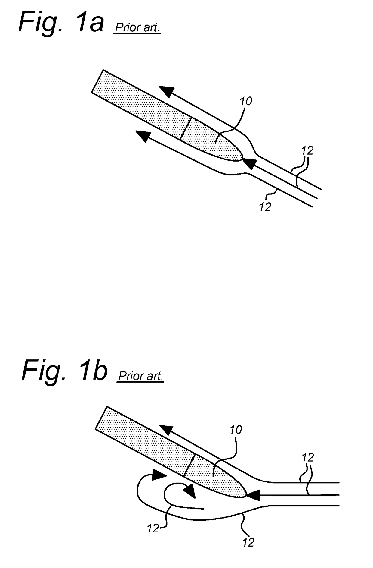
[0025]FIG. 1a is a view of a prior art blade 10 aligned to incoming flow, and FIG. 1b is a view of prior art blade 10 not aligned to incoming flow. FIGS. 1a-1b include arrows 12 indicating flow around blade 10. Blades for impellers are typically designed to align with a set incoming flowrate at a specific rotation speed, as shown in FIG. 1a. When a condition occurs where the blade is not aligned, either due to a different flowrate, a different rotation speed or both, flow separation can occur. This flow separation occurs when the angle between the blade and the incoming flow becomes too large, and causes the flow 12 to no longer follow blade 10 contour and detach from blade 10 surface. This flow separation, as shown in FIG. 1b, can result in high energy losses within the flow, significantly reducing the energy efficiency of the pump in which the blade and impeller rotate.

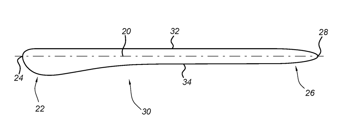
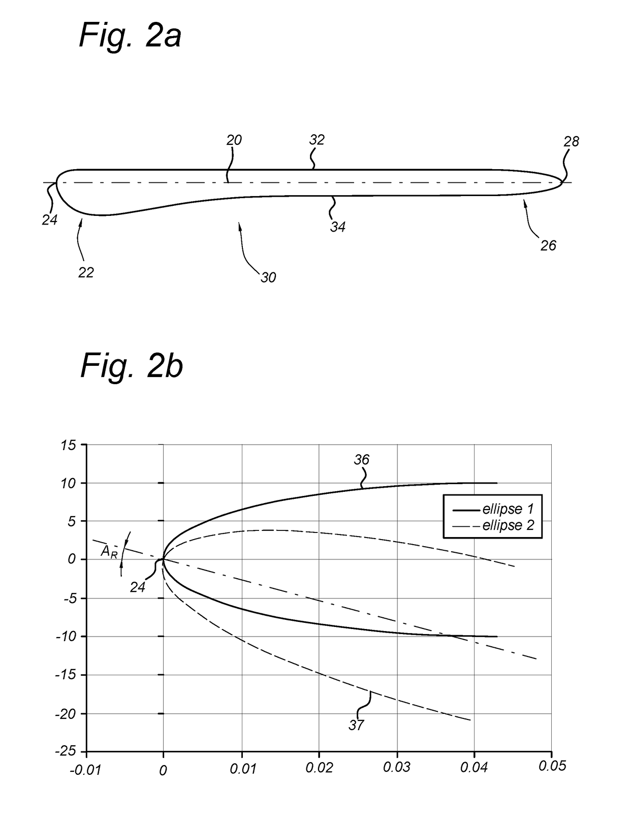
[0026]FIG. 2a is a cross-sectional view of an impeller blade 20 with a specific profile to encourage flow to rema...


PUM


Abstract

A blade for an impeller comprises a blade with a front portion with a leading edge and a trailing portion with a trailing edge joined by spaced apart pressure and suction sides to form an exterior blade surface. The blade pressure side is formed from an outer envelope of a first blade profile aligned in a first position; and at least a part of the front portion of the blade suction side is formed by rotating the first blade profile around the leading edge to match an angle of the incoming flow at a lower flowrate condition of the impeller.

Description

BACKGROUND[0001]Centrifugal pumps are typically designed for a specific flowrate and rotation speed. At this condition, referred to as the best efficiency point, the front portion of the impeller blades are aligned with the incoming flow, as shown in FIG. 1a. [0002]Beyond the best efficiency point, a variety of different types of blades are designed for use in centrifugal pumps for better performance during different pumping conditions and situations. For example, a number of patents and applications discuss varying the blade design in attempts to reduce solids being pumped from attaching to one of the edges of the blade. One such application is U.S. Pat. App. Pub. No. 2014 / 0079558 A1, which shows an impeller that is specially suited for pumping fibrous suspensions, like paper making stock. The impeller is formed to have vanes with a rounding or thickened part with a thickness greater than the central region of the vane to avoid fibers adhering to the edge of the vane. Similarly, GB...

Claims


Application Information

Patent Timeline
IPC IPC(8): F04D29/24
CPCF04D29/242F05D2240/303F05D2240/306F04D29/24
Inventor MUNTS, EDWIN ALBERT
Owner IHC HOLLAND NV
Why Eureka
Try Eureka