Connector

Inactive Publication Date: 2012-04-19
ASUSTEK COMPUTER INC
View PDF14 Cites 8 Cited by
  • Summary
  • Abstract
  • Description
  • Claims
  • Application Information

AI Technical Summary

Benefits of technology

[0009]Compare to the signal pins of the connectors, longer power pins, longer ground pins and shorter signal pins would achieve the hot plug function, which ensures

Problems solved by technology

However, as the conventional connectors only transmits the signal from the motherboard to a bus then given out via an external connecting port with “hot plug” function support

Method used


Image

  • Connector
  • Connector
  • Connector

Examples


Embodiment Construction

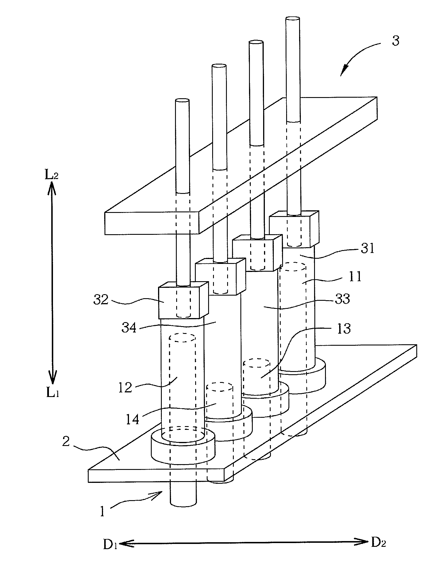
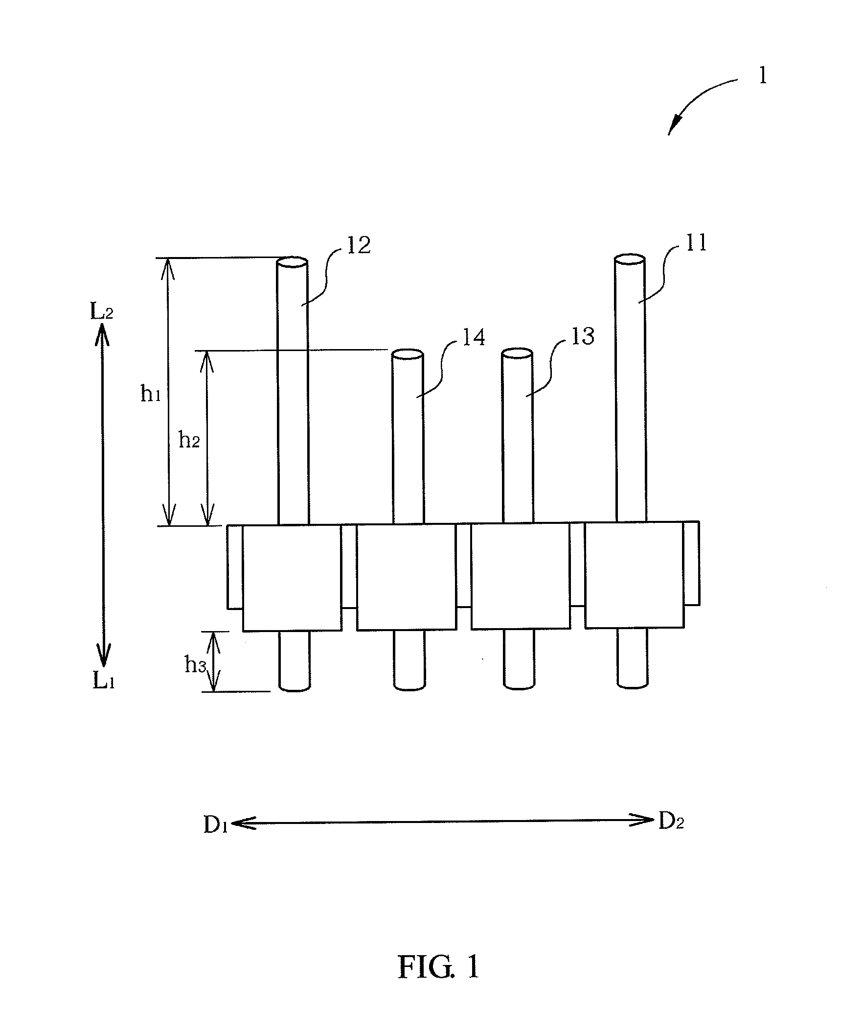
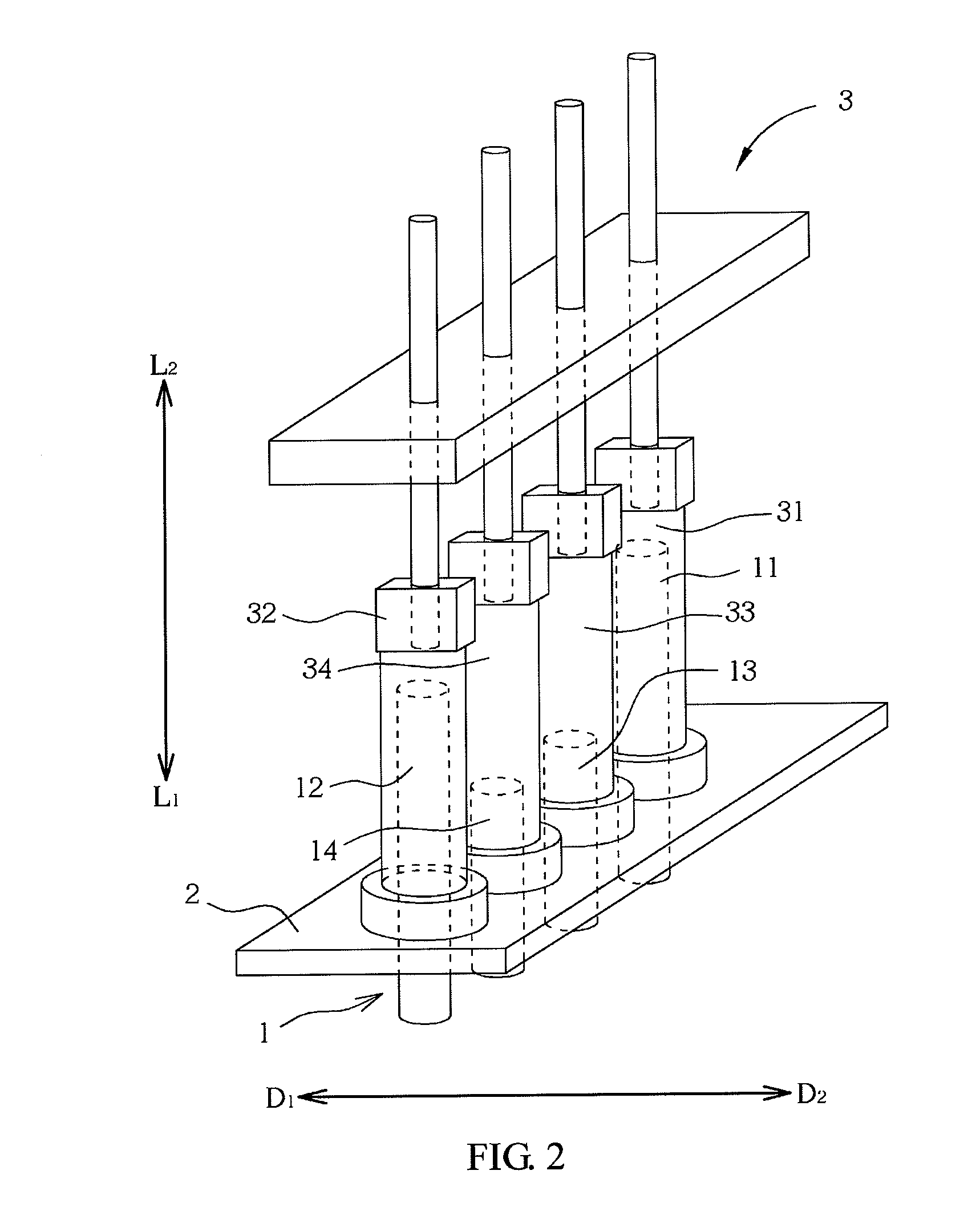
[0015]FIG. 1 is a schematic diagram showing a side view of a connector 1 in a first embodiment. FIG. 2 is a schematic diagram showing that the connector 1 in the first embodiment is disposed at a circuit board 2. In the first embodiment, the connector 1 is disposed at the circuit board 2 via dual in-line package (DIP). The circuit board 2 may be a motherboard of a computer system, a circuit board of an expansion card, or a printed circuit board with other applications. The connector 1 disposed at the circuit board 2 for selectively connected to other electronic elements or devices such as an expansion card, a connecting port or an input / output (I / O) port. The connector 1 includes a plurality of metal pins 11 to 14. The thickness of a common printed circuit board is approximately at 1.6 mm. Consequently, when the connector is disposed at the circuit board 2 via the DIP, the length h3 of each pin 11 to 14 passing through the circuit board 2 is longer than the thickness of the circuit ...


PUM


Abstract

A connector is disposed at a circuit board and utilized for connecting to an external connecting port which is detachably connected to the connector of the circuit board via a connecting terminal, so as to provide an expansion connecting channel between the connecting port and the circuit board. The connector includes the plurality of power pins and the plurality of signal pins, and the length of the power pins is longer than that of the signal pins along an assembling direction of the connecting terminal to the connector. Thus, when the connecting terminal is removed from the connector, the connecting terminal is detached from the connecting pins first to stop the data transmission to avoid the data loss or damage due to the power off, thus to achieve the “hot-plug” function, and also to avoid the damage of the host or the external device.

Description

CROSS REFERENCE TO RELATED APPLICATIONS[0001]This Non-provisional application claims priority under 35 U.S.C. §119(a) on Patent Application No(s). 099134864 filed in Taiwan, Republic of China on Oct. 13, 2010, the entire contents of which are hereby incorporated by reference.BACKGROUND OF THE INVENTION[0002]1. Field of Invention[0003]The invention relates to a connector.[0004]2. Related Art[0005]To expand the functions of a motherboard of personal computers, service hosts or other systems, users may insert an expansion card to the extended slot of the motherboard, or dispose a plurality of extended connectors at the motherboard. The connectors includes a plurality of metal pins (which usually include power pins and signal pins) extended from the motherboard, and they are connected to an input / output (I / O) port at the rear panel of the host or various connecting port at a casing via a flexible signal cable.[0006]Some connecting ports have the function that support “hot plug” between ...

Claims


Application Information

Patent Timeline
IPC IPC(8): H01R12/71
CPCH01R12/718
Inventor WU, LI-CHIENHUANG, PAI-CHING
Owner ASUSTEK COMPUTER INC
Why Eureka
Try Eureka