Banding device

Inactive Publication Date: 2012-04-26
BEN CLEMENTS & SONS
View PDF10 Cites 0 Cited by
  • Summary
  • Abstract
  • Description
  • Claims
  • Application Information

AI Technical Summary

Benefits of technology

[0007]At least one finger on the transfer arm of the transfer assembly is capable of moving between a first position and a second position to accommodate a variety of sizes of elastic tubing. Band length is controlled by a feed roller within the feed assembly. A drive shaft is affixed to a block mounted to the housing. The block is adjustably positioned on the housing to extend the drive length which increases the rotation of the drive shaft which in turn changes the r

Problems solved by technology

The prior art device has been satisfactory, however, it suffers from the disadvantage that the same head which receives the band is the head which places the band on the bundle.
Therefore, the device is limited to bundling only one band for each repeated cycle of the operation of the device, i.e. the object must be removed and reinserted for each additional band.
Furthermore, it is difficult to consistently cut an elastic tube as it is fed.
Elastic materials, st

Method used


Image

  • Banding device
  • Banding device
  • Banding device

Examples


Embodiment Construction

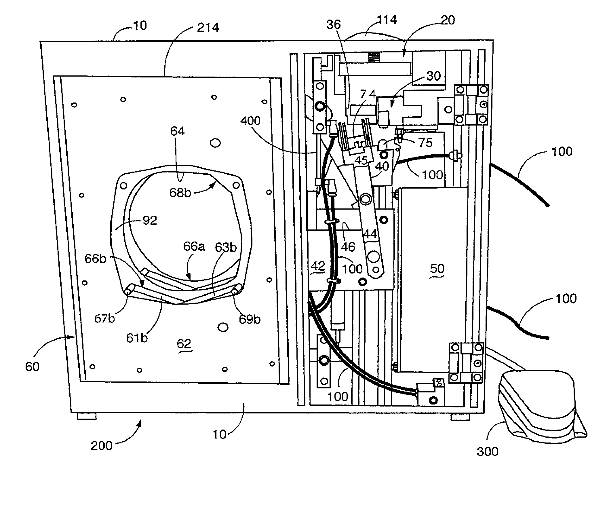
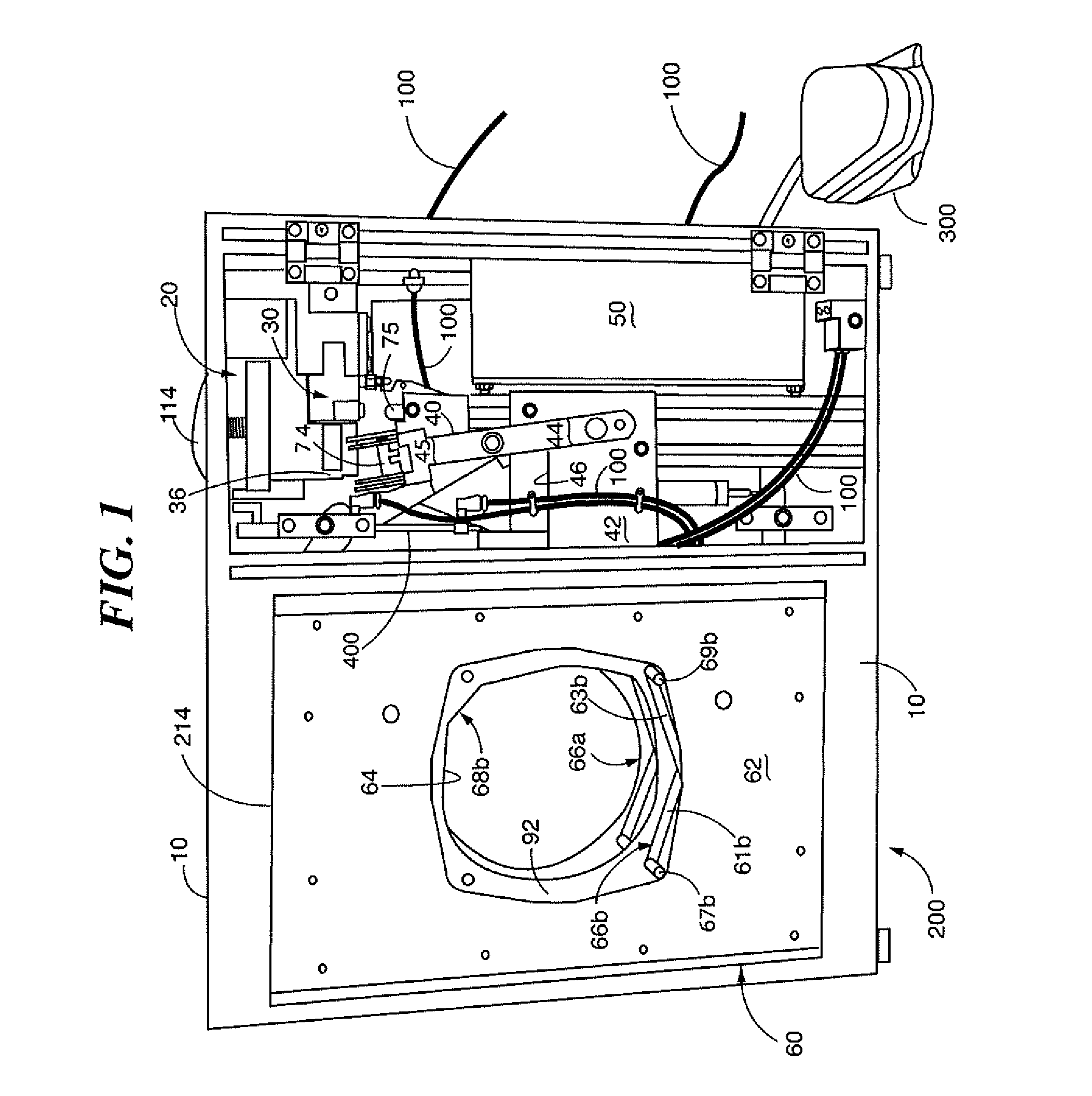
[0018]Reference is made to FIGS. 1 and 2 in which a banding device generally indicated as 200 includes a frame 10. A feeding assembly, generally indicated as 20, is disposed within frame 10 adjacent a wall 12 of frame 10. As more particularly seen in FIG. 2, an input port 22 is formed in wall 12 of frame 10 and is dimensioned to receive a raw stock of elastic tubing 114 which will then be formed into bands 14 as discussed below.

[0019]Portal 22 forms the entrance of a feed path. Feed assembly 20 includes a drive assembly generally indicated as 24 downstream of portal 22 for receiving tubing 114 and pulling tubing 114 through portal 22. In a preferred nonlimiting embodiment, drive assembly 24 is formed as a drive roller 26 and idler roller 28 (FIG. 6) which operate for a predetermined number of rotations (including less than 1) which are a function of time or speed, which, as is known in the art, corresponds to a predetermined feed length of tubing 114 into frame 10. Adjusting roller ...


PUM

PropertyMeasurementUnit
Lengthaaaaaaaaaa
Timeaaaaaaaaaa
Angleaaaaaaaaaa

Abstract

A banding device includes a frame. A feeding assembly is mounted on the frame for feeding elastic tubing into the frame. A transfer assembly disposed within the frame includes transfer arm and fingers. The fingers receive the rubber tubing as fed. A cutting assembly is disposed between the transfer assembly and the feeding assembly for cutting the tubing into bands. The fingers of the transfer assembly move between a first closed position for receiving the band and a second open position for opening the band. The transfer arm is moveable between a first position for receiving the band and a second position for transferring the band. A banding assembly disposed at the second position receives the band from the transfer assembly. The banding assembly stretches the band and receives an item to be bundled within the band. The banding assembly releases the band about the bundle.

Description

CROSS REFERENCE TO RELATED APPLICATIONS[0001]This application claims the benefit of priority to U.S. Provisional Application No. 61 / 406,485 filed Oct. 25, 2010.BACKGROUND OF THE INVENTION[0002]This invention is directed to a device for bundling items by applying elastic bands onto objects to be held together or immobilized.[0003]It is known in the art to bunch certain produce such as broccoli, celery, industrial products such as moldings and extrusions, or the like by applying elastic bands about several items. Exemplary prior art devices are represented by U.S. Pat. No. 7,257,934. In this device, at least one elastic tube is fed into the banding device. The tube is cut at predetermined lengths to form elastic bands. Once cut into bands, the bands fall onto fingers which separate to open the band to receive an article therein. Upon activation, the fingers release the band which surrounds the product forming the bundle. The product is then removed from the frame. The processes may be...

Claims


Application Information

Patent Timeline
IPC IPC(8): B65B13/16B65B13/02
CPCY10T29/53657B65B13/022Y10T83/0448Y10T83/0596Y10T83/2198Y10T83/704
Inventor CORBIN, JOHN
Owner BEN CLEMENTS & SONS
Why Eureka
Try Eureka