Paper pickup structure of paper feeding device

Active Publication Date: 2012-04-26
TECO IMAGE SYST
View PDF3 Cites 8 Cited by
  • Summary
  • Abstract
  • Description
  • Claims
  • Application Information

AI Technical Summary

Benefits of technology

[0009]In the present invention, the limiting member is made of an elastic material; one end thereof is fixed at a preset position, and the other end thereof is combined with the combination member of the rotating arm when the rotating arm forwardly rotates to a first position and is separated from the combination member during the reverse rotation of the rotating arm, and afterwards, the rotating arm forwardly rotates, so that the second gear on the rotating arm drives the third gear to rotate, and the third gear drives the paper pickup wheel to rotate. Compared with the conventional paper pickup structure, the structure of the present invention is rather simple, and the components thereof are fewer, so that not only can the manufacturing cost of the components be reduced greatly, but the assembly cost thereof is also reduced, while no external component is required to control its operation, and the heat fade problem in the conventional paper pickup structure can be solved.

Problems solved by technology

In a paper pickup mechanism of the conventional RADF, an electronic clutch is mostly used to control a paper pickup time of a next manuscript during double-sided scanning, which is convenient, but too costly.
In addition, a heat fade problem may occur in the conventional paper pickup mechanism due to long-time use, and burning may even be caused.
Furthermore, the use of the conventional paper pickup mechanism may increase the power of the machine, and thus a design purpose of low power requirements for modern products cannot be achieved.

Method used


Image

  • Paper pickup structure of paper feeding device
  • Paper pickup structure of paper feeding device
  • Paper pickup structure of paper feeding device

Examples


Embodiment Construction

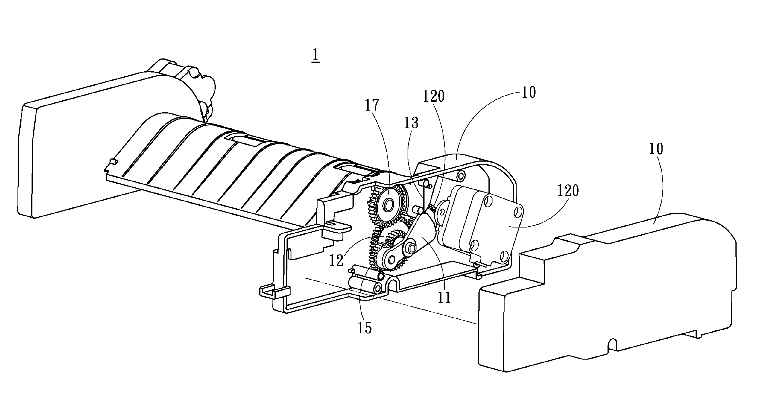
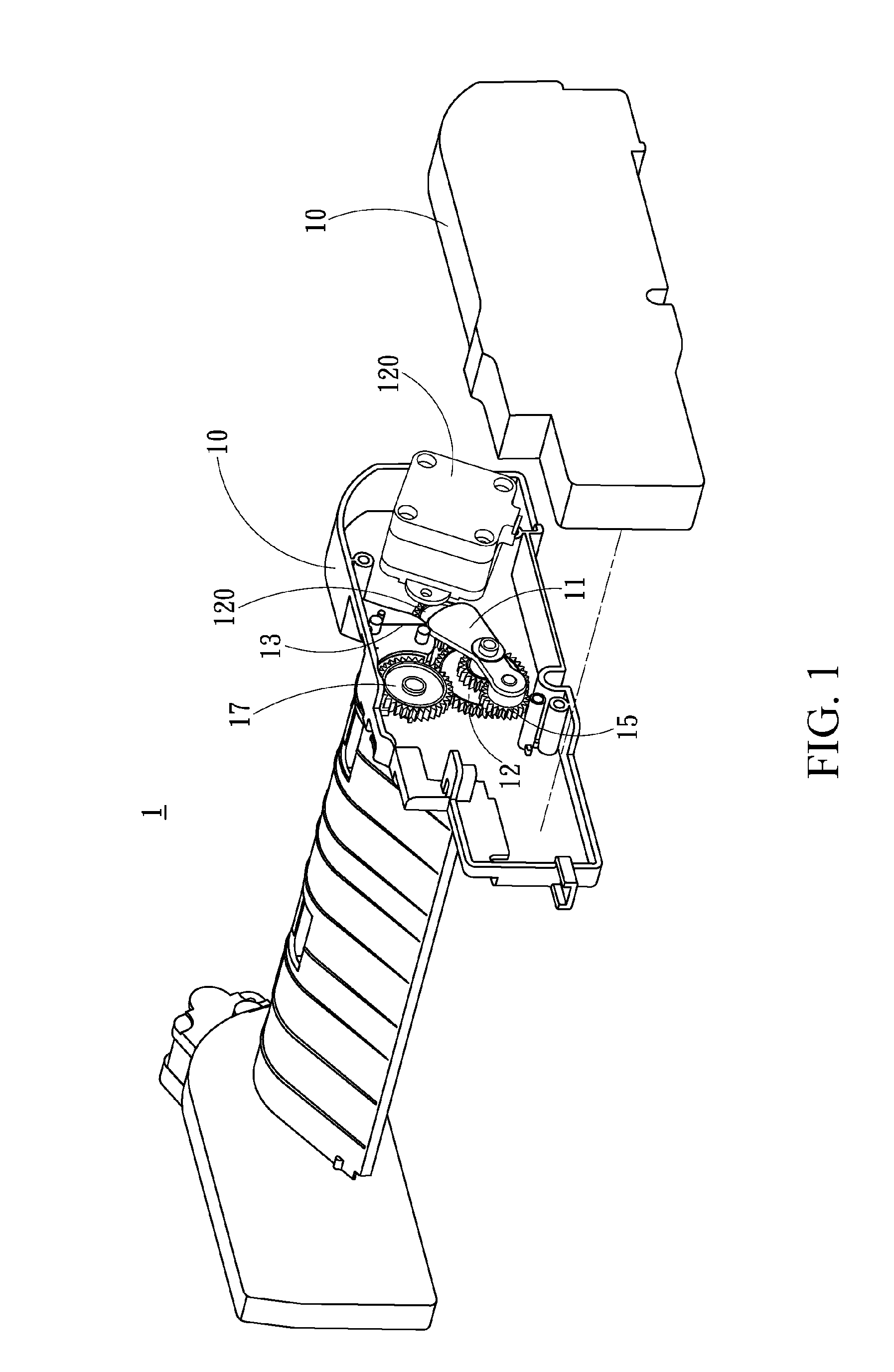
[0024]Please refer to FIGS. 1, 2, 3 and 4, in which a paper pickup structure of a paper feeding device according to the present invention is shown.

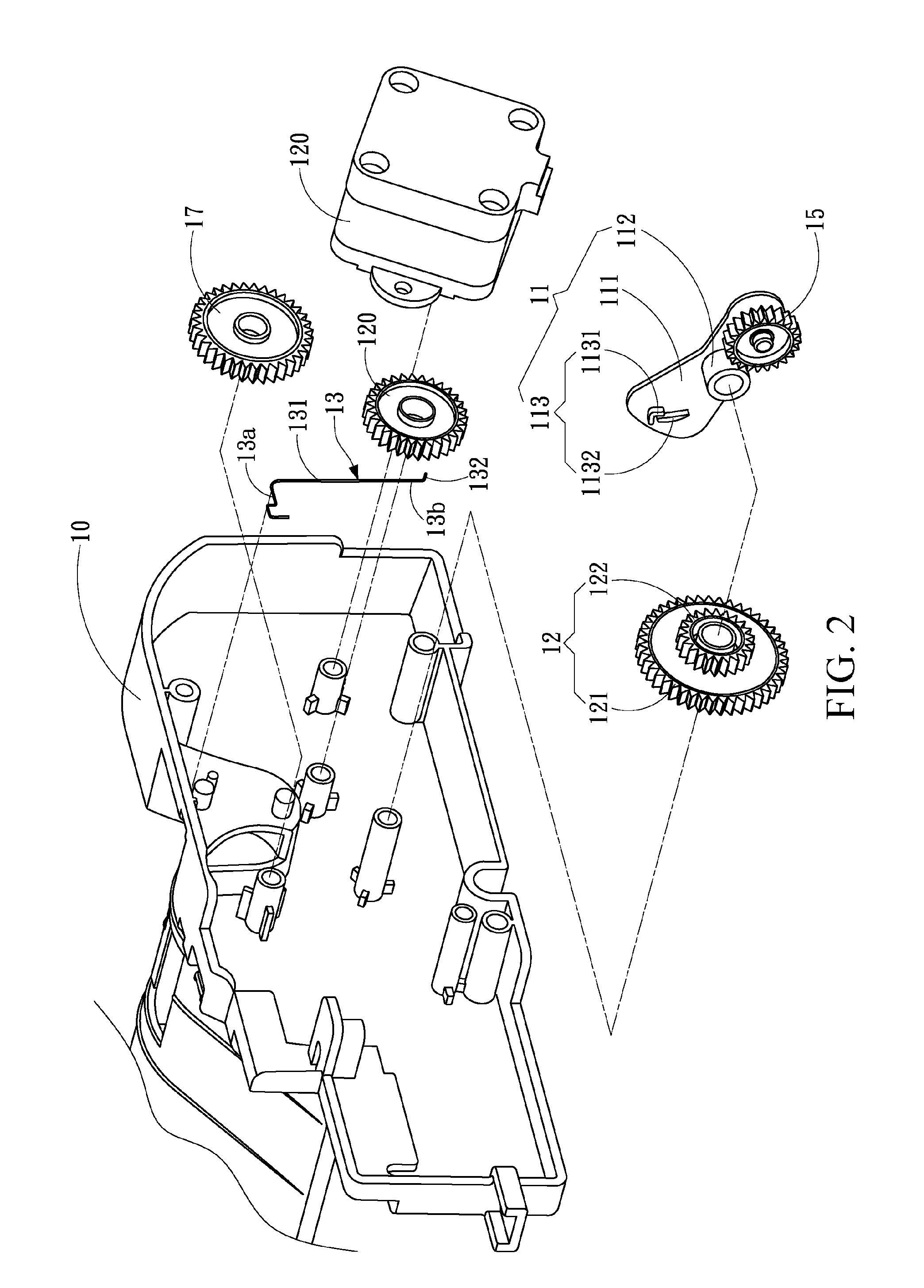
[0025]The paper pickup structure 1 of the paper feeding device includes a rotating arm 11, a first gear 12, a limiting member 13, a second gear 15, and a third gear 17.

[0026]The rotating arm 11 is mainly formed by a base 111, a connection portion 112, and a combination member 113. Herein, the base 111 is a long plate, the connection portion 112 and the combination member 113 are respectively located on two sides of the base 111, and the base 111 extends outward from a position where the combination member 113 is disposed, so that the base 111 is approximately in a J shape on the whole (as shown in FIG. 2), and the rotating arm 11 may rotate about the connection portion 112.

[0027]The first gear 12 is combined with the connection portion 112, and is driven by a driving module 120 to be switched between a forward rotation state and a reverse...


PUM


Abstract

A paper pickup structure of a paper feeding device is provided. The paper pickup structure includes: a rotating arm, including a connection portion, a base, and a combination member, in which the connection portion and the combination member are located on the base; a first gear, combined with the connection portion to be switched between a forward rotation state and a reverse rotation state, so as to drive the rotating arm to rotate; a limiting member, located on the rotating arm, in which one end of the limiting member is combined with the combination member of the rotating arm, or one end of the limiting member is separated from the combination member through the rotation of the rotating arm; a second gear, located on the base; and a third gear, driven by the second gear to rotate when the rotating arm rotates to a predetermined position.

Description

CROSS-REFERENCES TO RELATED APPLICATIONS[0001]This non-provisional application claims priority under 35 U.S.C. §119(a) on Patent Application No. 99136231 filed in Taiwan, R.O.C. on Oct. 22, 2010, the entire contents of which are hereby incorporated by reference.BACKGROUND[0002]1. Technical Field[0003]The present invention relates to a paper pickup structure, and more particularly to a paper pickup structure of a paper feeding device.[0004]2. Related Art[0005]With the change of technology each passing day, office machines associated with computer peripherals, such as printers, photocopiers, scanners, and fax machines, can help improve information processing efficiency, and are therefore increasingly popular. Furthermore, with the development of multi-functional machine technology, more and more office machines have faxing, scanning, photocopying, and printing functions. Office machines not only have multiple word processing capabilities, but have also become lighter. Moreover, their ...

Claims


Application Information

Patent Timeline
IPC IPC(8): B65H3/06
CPCB65H3/0669B65H2402/5441B65H2801/06B65H2403/942B65H2403/422B65H2402/54
Inventor CHUNG, MING-CHIEHTSAI, PO-WEN
Owner TECO IMAGE SYST
Why Eureka
Try Eureka