Angled Guide Plate for a Rail Profile

a technology of rail profile and guide plate, which is applied in the direction of railway tracks, roads, constructions, etc., can solve the problems of high component cost, high use of material, and low efficiency of the system, and achieve the effects of high component cost, high use of material, and low efficiency

Active Publication Date: 2016-08-18
SEMPERIT OSTE AMERIKANISCHE GUMMIWERKE AG
View PDF1 Cites 0 Cited by
  • Summary
  • Abstract
  • Description
  • Claims
  • Application Information

AI Technical Summary

Benefits of technology

This patent describes a new type of guide plate and track arrangement for a machine tool. The guide plate is angled, which means it is not flat, and this design has several advantages over traditional guides. One advantage is that it allows for smoother and more precise motion of the machine tool. Another advantage is that it reduces the amount of force needed to move the machine tool. The patent also explains how these single design features can be combined with each other to create different machine tool configurations. Overall, this new design improves the performance of machine tools and allows for more flexibility in their use.

Problems solved by technology

However, the angled guide plates known from the prior art made of plastic do not have a design appropriate for plastic and the costs thereof are not optimized.
As a consequence, the use of material is high and there result high component costs, long cycle times for manufacturing that result in low manufacturing capacities as well as great efforts for ensuring the geometry and the mechanical properties due to the construction not appropriate for plastic.
If such recesses are not accurately aligned with the rail, if they thus are not accurately parallel, it can come to tensions when arranging the angled guide plate.

Method used


Image

  • Angled Guide Plate for a Rail Profile
  • Angled Guide Plate for a Rail Profile
  • Angled Guide Plate for a Rail Profile

Examples


Embodiment Construction

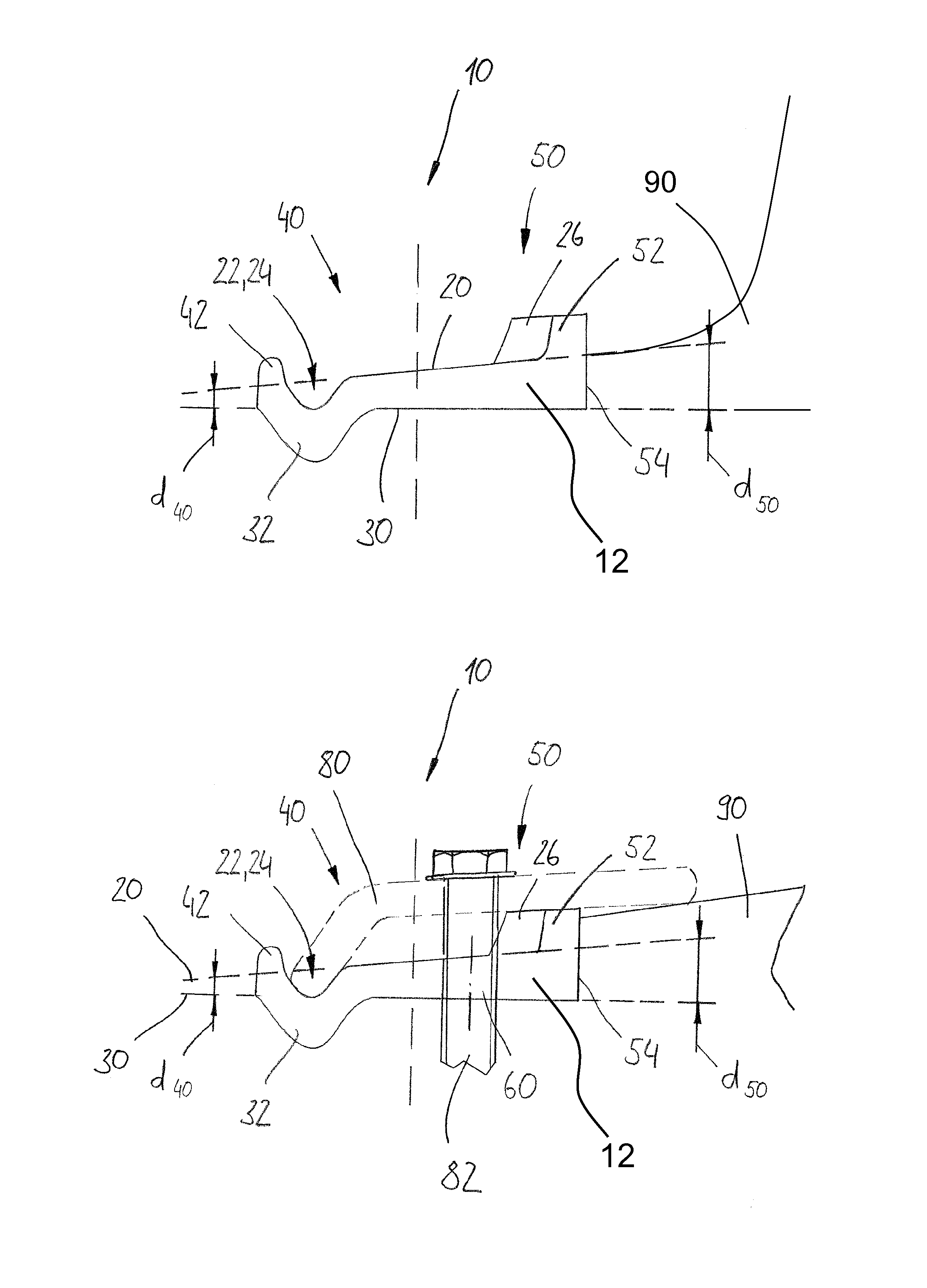
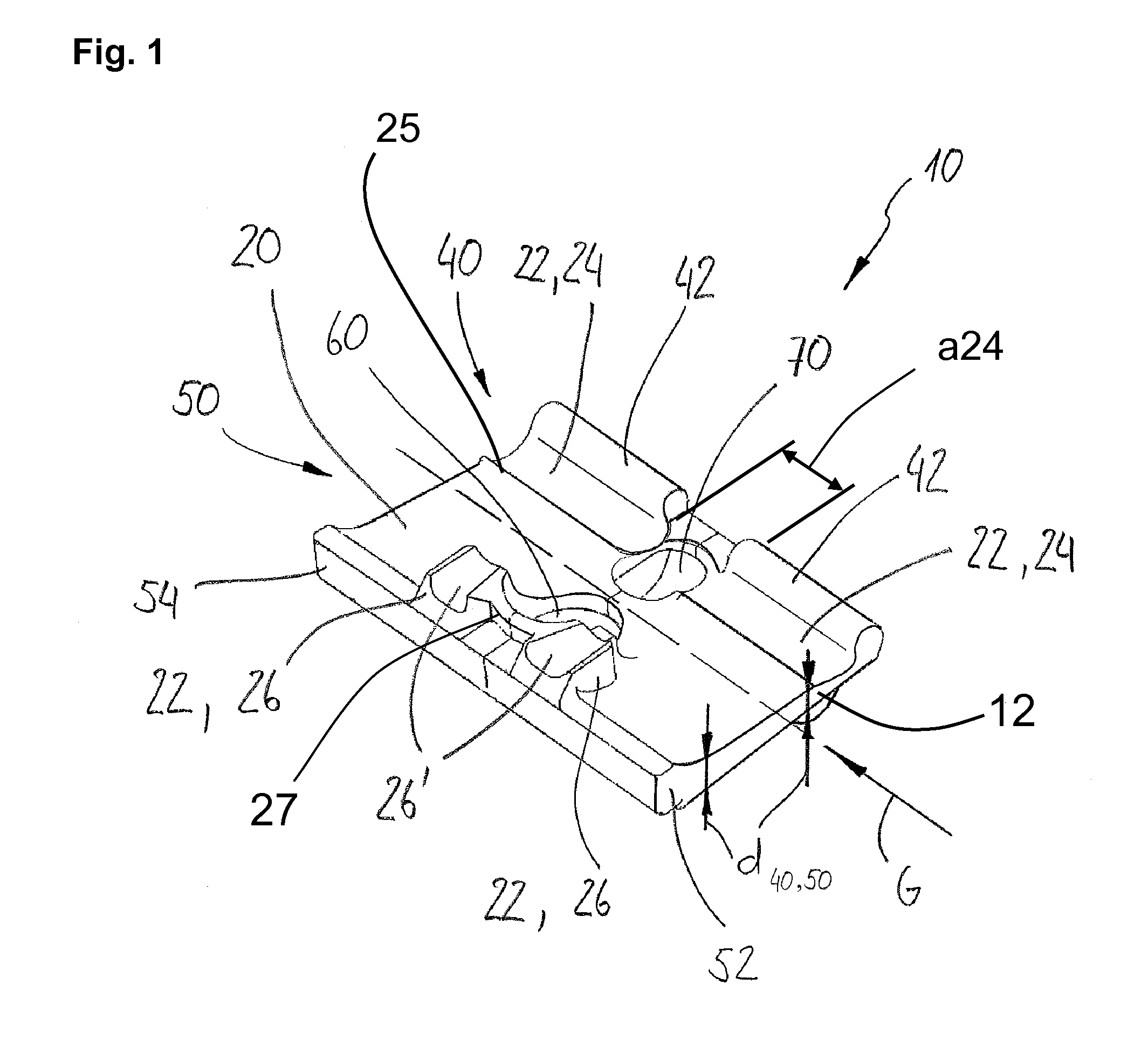
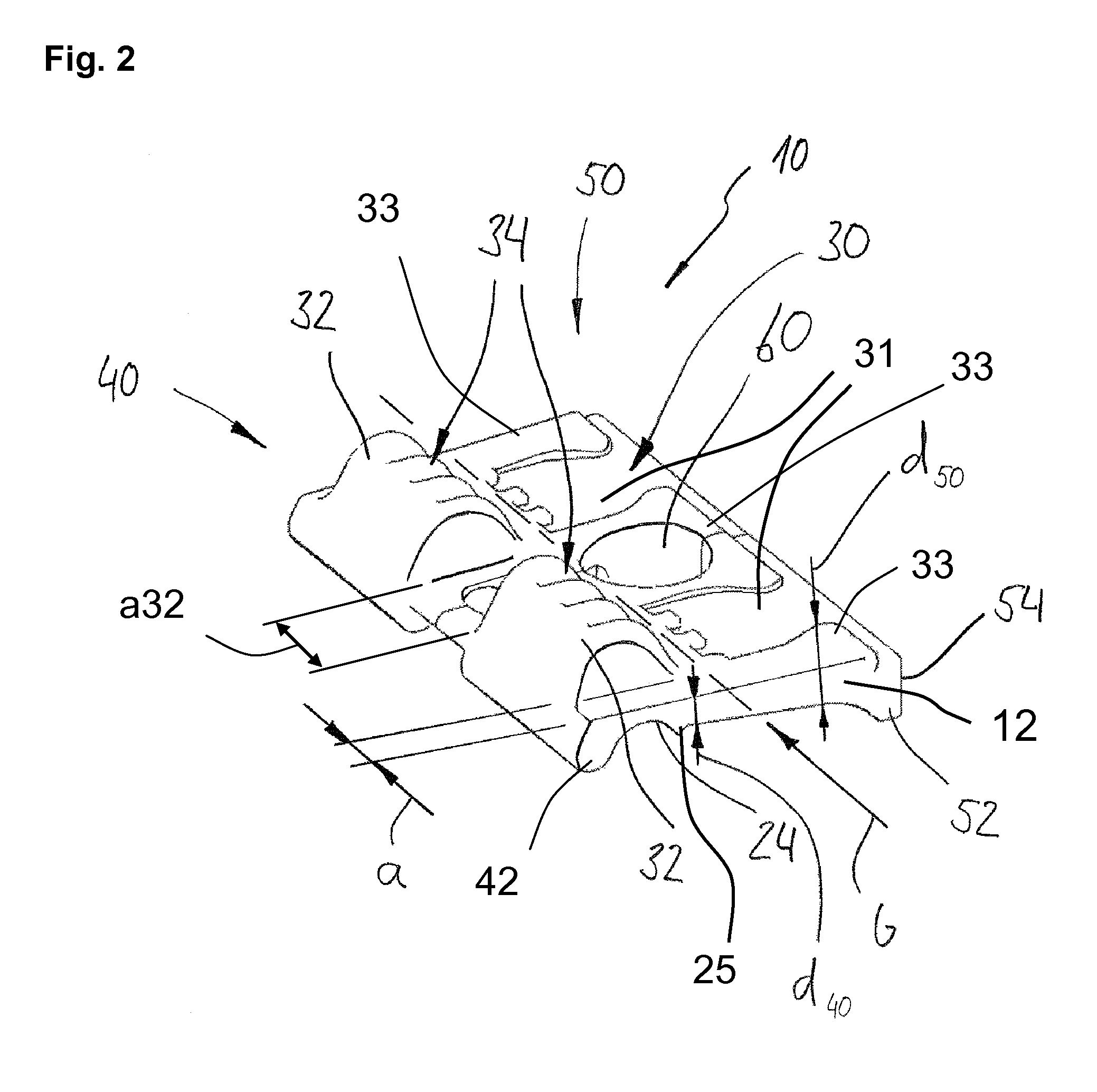
[0035]FIG. 1 shows a perspective view of a preferred embodiment of an upper side 20 of an angled guide plate 10. The angled guide plate 10 has a basic body 12 and extends along a track direction G. A (imaginary) separation line between a guide region 40 and a supporting region 50 is represented as a dotted line along the track direction G. It can be clearly seen that a thickness d50 (selected as an example) of the supporting region 50 is bigger than a thickness d40 (selected as an example) of the guide region 40. The supporting region 50 has a force introduction area 22 configured by two protrusions 26. The protrusions 26 are connected with each other along the track direction G by a web 27. Furthermore, the supporting region 50 has a heel 52 towards the rail (that is not represented here) that increases a stop surface 54 of the basic body 12 that extends substantially perpendicularly to an underside 30. The guide region 40 has two force introduction areas 22 configured as recesses ...


PUM


Abstract

An angled guide plate, in particular for rail fastening systems, includes a basic body that has an upper side and an underside, wherein the underside is designed for arranging on a further element, in particular a railway sleeper, whereas the upper side describes an opposite plane substantially transversely to the railway sleeper and wherein the angled guide plate consists of a guide region and a supporting region, wherein the guide region and the supporting region extend substantially parallel and adjacent to one another in a direction transverse to a track direction, and wherein the upper side and the underside are spaced apart from one another so that a thickness of the supporting region, as measured substantially perpendicularly to the underside, is larger, at least in part, than a thickness of the guide region.

Description

BACKGROUND OF THE INVENTION[0001]This invention relates to an angled guide plate as well as a track arrangement, in particular for rail fastening systems.[0002]Angled guide plates are known from the prior art. They are used for fastening systems for railway superstructures. In particular, the rails are fixed and guided with angled guide plates of the type in question. For this purpose, the angled guide plates are placed on (railway) sleepers, generally made of concrete, and screwed with these sleepers by means of already cast-in dowels with screws, together with corresponding tension clamps that press from above onto a rail base of the corresponding rail. As a result, extreme forces act on the angled guide plate. While the angled guide plates were made of cast iron in the past, it is known today to make them of plastic. However, the current angled guide plates made of plastic do not have a design suitable to the material and their implementation is not appropriate for plastic. This ...

Claims


Application Information

Patent Timeline
Patent Type & Authority Applications(United States)
IPC IPC(8): E01B9/60
CPCE01B9/60E01B9/28E01B9/00E01B9/42E01B9/685
Inventor MIESSBACHER, HERWIGREINTHALER, STEFANSCHONGRUNDNER, MARIO
Owner SEMPERIT OSTE AMERIKANISCHE GUMMIWERKE AG
Why Eureka
Try Eureka