Connector system with airflow control

a technology of airflow control and connector system, which is applied in the direction of coupling device connection, electrical apparatus, cooling/ventilation/heating modification, etc., can solve the problems of less airflow and overheating of some modules

Active Publication Date: 2012-04-26
MOLEX INC
View PDF5 Cites 42 Cited by
  • Summary
  • Abstract
  • Description
  • Claims
  • Application Information

AI Technical Summary

Benefits of technology

[0006]A connector assembly includes a cage with a port and a housing positioned in the cage. The cage has a rear wall and a front face. An air passage associated with the port extends between the rear wall and the front face. The air passage includes an airflow restrictive section and is configured so that an airflow impedance of the air passage does not increase in an undesira

Problems solved by technology

However, the cage, while providing increased shielding, typically also results in less airflow.
In addition, since all of the ports of a connector sys

Method used


Image

  • Connector system with airflow control
  • Connector system with airflow control
  • Connector system with airflow control

Examples


Embodiment Construction

[0021]The following description is intended to convey the operation of exemplary embodiments to those skilled in the art. It will be appreciated that this description is intended to aid the reader, not to limit the invention. As such, references to a feature or aspect are intended to describe a feature or aspect of an embodiment of the invention, not to imply that every embodiment must have the described characteristic. Furthermore, it should be noted that the depicted detailed description illustrates a number of features. While certain features have been combined together to illustrate potential system designs, those features may also be used in other combinations not expressly disclosed. Thus, the depicted combinations are not intended to be limiting unless otherwise noted.

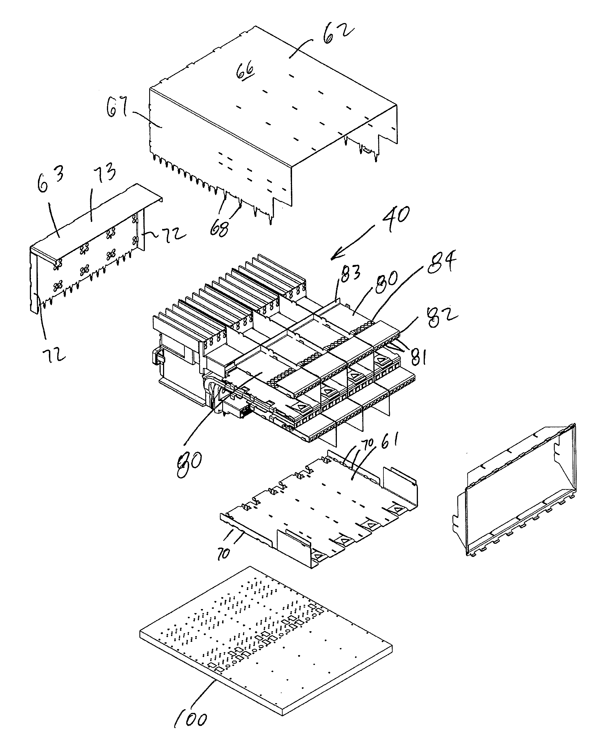
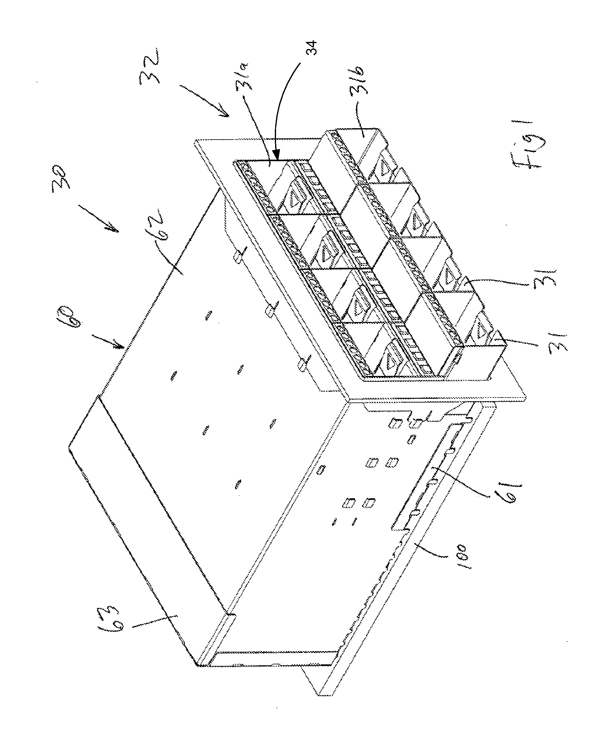
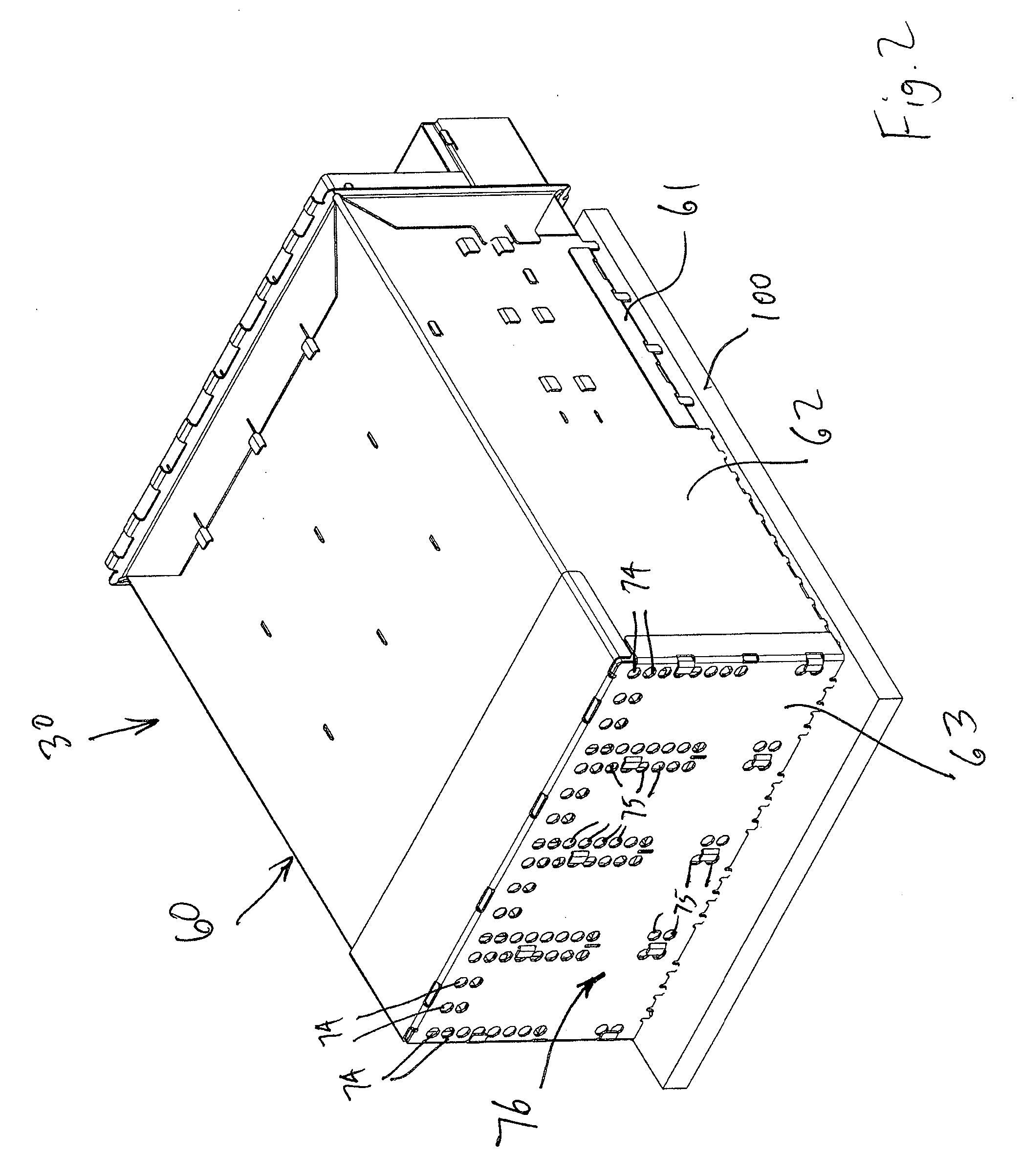
[0022]Referring to FIGS. 1-2, a connector assembly 30 is illustrated mounted on a circuit board 100. The connector assembly 30 is depicted as providing a 2×4 array of ports 31, meaning it has two stacked ports 3...


PUM


Abstract

A connector assembly includes a cage with a plurality of ports for receiving modules. An air passage is associated with each port and extends from a rear wall of the cage through a front face of the cage. The air passage way is configured to provide relatively consistent airflow regardless of whether or not a module is inserted into the corresponding port.

Description

RELATED APPLICATIONS[0001]This Application claims priority to U.S. Provisional Application No. 61 / 406,517, filed Oct. 25, 2011, which is incorporated herein by reference in its entirety.FIELD OF THE INVENTION[0002]This disclosure relates generally to high speed connector systems and, more particularly, to airflow control through a high speed pluggable connector system.BACKGROUND[0003]In computer systems, such as servers, routers and other data handling devices, there is a trend towards increased system speeds and performance as well as greater densities of components. In general, the increased performance and higher densities result in an increased need for cooling of the servers and their components. The data handling devices typically cool their components by drawing or forcing air through the components, such as a chassis of a server, through the use of fans or other air moving devices.[0004]Data transmission to and from the data handling devices often occurs through cable assemb...

Claims


Application Information

Patent Timeline
IPC IPC(8): H05K7/20
CPCH01R13/6587H05K7/20709H05K7/20209H05K7/20145
Inventor REGNIER, KENT E.
Owner MOLEX INC
Why Eureka
Try Eureka