
Bag-valve-mask

Active Publication Date: 2018-10-18
COMPACT MEDICAL SOLUTIONS LLC
View PDF5 Cites 3 Cited by
  • Summary
  • Abstract
  • Description
  • Claims
  • Application Information

AI Technical Summary

Benefits of technology

The invention is a compact self-inflating bag with a unique valve body that reduces the size of the device and makes it more portable. The bag has two layers of material with an airspace in between them, which can be inflated or pumped air into. The valve body has a two-way valve and a filter to protect the patient. The mask is collapsible and made of a thin, lightweight material. The technical effects of the invention are reduced size, portability, and safety.

Problems solved by technology

However, BVMs are not commonly on hand in most public and private settings.
Outside of an ambulance, a hospital or similar clinical location, BVMs are not typically readily available.
Self-inflating or self-expanding bags are bulky.
This angle is ideal for function, but not for creating a compact device.
The mask is similarly bulky and typically employs a rigid plastic triangular-shaped device with a soft rubber balloon about a perimeter that interfaces with and forms a seal around the mouth and nose of a victim.
Each of these components is bulky in its own right and together, these form a device that is too large and obtuse to be carried in public by individuals who are trained to use them.
Thus, when an emergency arises in most non-clinical settings, a BVM is not typically available until after an ambulance has arrived.
This results in bag-valve-masks that are suitable for one-time use, due to the device losing functionality after its use.

Method used


Image

  • Bag-valve-mask
  • Bag-valve-mask
  • Bag-valve-mask

Examples


Embodiment Construction

[0039]For the purpose of explanation, the terms “front”, “back”, “left”, “right”, “upper”, “lower”, “top”, “bottom”, and similar terms shall correspond to the device as positioned in the figures (above / below). The device may assume alternate orientations other than those shown. It is understood that the device characterized in the attached drawings and described thereafter are exemplary orientations of the innovative concepts defined in the claims section of this patent. Hence, the specific physical characteristics shown are not to be considered limiting unless explicitly stated. The device shown may alter in size depending on its need.

[0040]The following description relates to above figures.

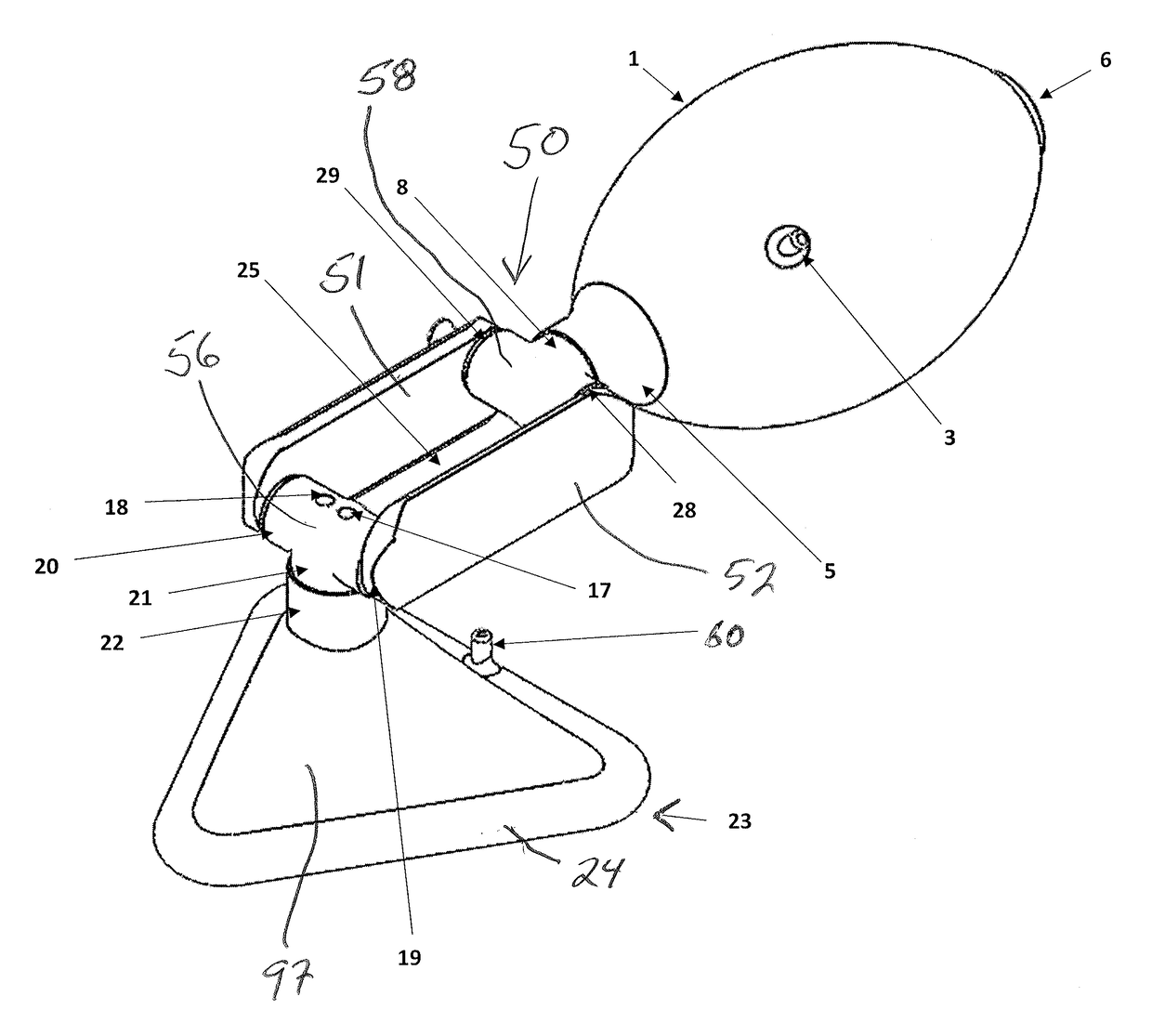
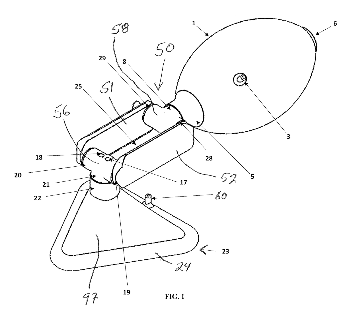
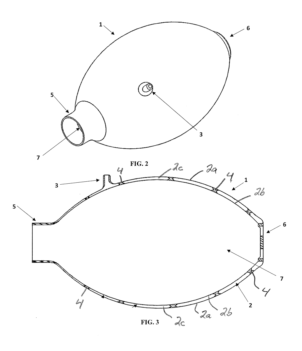
[0041]With reference to the Figures, the bag-valve-mask described and shown herein includes a self-inflating bag 1 as shown in FIG. 1 comprised of an inflatable (or in some other way expandable) bilayer 2, including an outer layer 2a and an inner layer 2b, as shown in FIG. 3. This inflatable bil...


PUM


Abstract

A respiratory assisting device comprising of an expandable bag which has a bilayer that can be inflated in order to give the bag a rigid and predetermined shape. The bag can then be compressed in order to displace inspiratory gas that is in the inner cavity and deliver it to the patient. The bag includes a one-way valve that passes through the bilayer allowing the inner cavity of the bag to fill with ambient air when the air within the cavity has been expended. The bag portion is connected to an air-tight hollow wall prism shape enclosure via a T-connector piece. This t-shaped connecting piece allows the air to pass through two manifold chambers that attach to another t-shaped connecting piece. One of the manifolds contains a pressure-release valve feature on the outer wall which vents air from the bag to the periphery if pressures within the system exceed a target pressure. The second t-connector piece has a two-way valve system within its walls to deliver the inspiratory air from the bag to inflate the patient's lungs while preventing exhaled air from the patient from entering back into the bag. Instead this expiratory air is vented into the periphery. Below the valve is a protective filter which serves as a safety mechanism to prevent the transmittance of any potentially dislodged components from within the device from being transferred down into the victim's airway. The air finally flows through a collapsible mask which can be inflated when needed to give it a rigid shape that conforms to the patient's face with the purpose of delivering and receiving rescue breaths. The t-shaped connector pieces are rotatable which permits the two inflatable portions of the device,the bag and the mask, to fold into the interior of section of the manifold enclosure for storage and transportation purposes.

Description

BACKGROUND OF THE INVENTIONField of the Invention[0001]The invention relates to a bag-valve-mask or resuscitator used to ventilate patients in a field setting.Background Art[0002]The present invention relates to the compactness and portability of a lifesaving medical device sometimes called a resuscitator or a bag-valve-mask.[0003]A bag-valve-mask (BVM) is a device used to temporarily push air into the lungs of a patient who is unconscious or otherwise unable to breathe on their own. These devices are found in hospitals and in ambulances throughout the country and in most developed parts of the world. A BVM is one of most fundamental pieces of lifesaving equipment.[0004]BVMs have existed for many years. The first such device was introduced by Dean R. Wallace in 1966 (U.S. Pat. No. 3,473,529). Numerous modifications and enhancements have been made to BVMs over the years, these include enhanced 2-way valves (ex. U.S. Pat. No. 5,109,840), the addition of a high-pressure relieving “pop-...

Claims


Application Information

Patent Timeline
IPC IPC(8): A61M16/08A61M16/00A61M16/06A61M16/10A61M16/20
CPCA61M16/0883A61M16/0084A61M16/20A61M16/0816A61M16/105A61M16/0622A61M16/0078A61M16/208A61M16/209
Inventor MERRELL, JONATHANSCOTT, ADAMNAYEE, DILLANPRAKASH, VARUNWAGNER, DALEGLASS, NATHAN
Owner COMPACT MEDICAL SOLUTIONS LLC
Learn More