
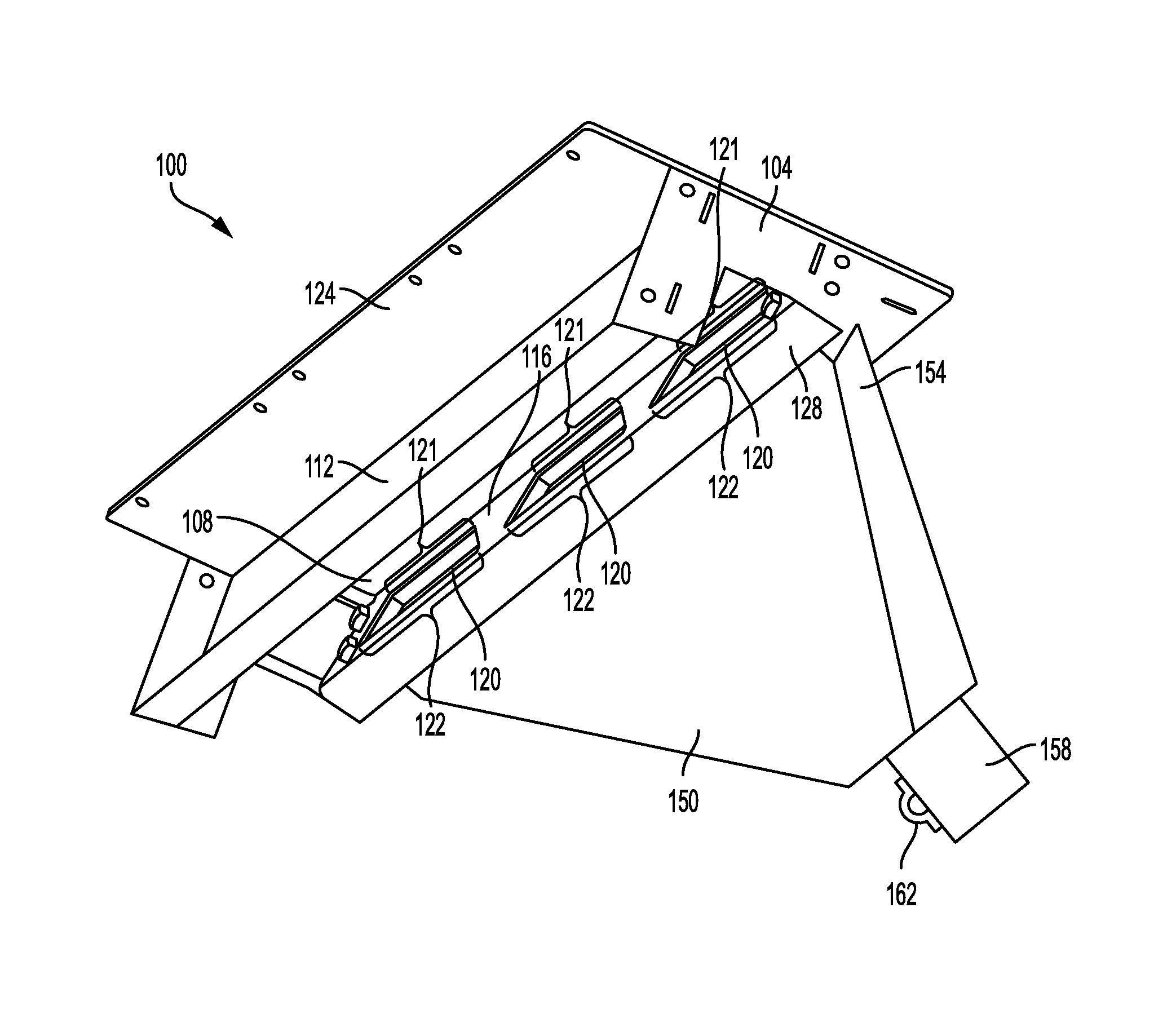
Dust containment unit manifold

a technology of dust containment manifold and manifold, which is applied in the direction of ventilation system, heating type, separation process, etc., can solve the problems of contamination, contamination cannot be released outside, and the inside gun firing range enclosure presents particularly difficult problems for proper ventilation, so as to improve the strength and stability of the dust containment manifold, and improve positioning. , the effect of maximizing airflow

Active Publication Date: 2016-07-21
ACTION TARGET
View PDF12 Cites 4 Cited by
  • Summary
  • Abstract
  • Description
  • Claims
  • Application Information

AI Technical Summary

Benefits of technology

The patent text describes a device that helps contain dust and fine particles during the cutting of gun bullets. The device has a solid side and a perforated side, which can be angled to prevent the collection of debris on the perforated side. The device can also be easily installed on-site using airflow heads. The technical effect of this invention is to provide a more efficient and effective way to contain dust and fine particles during the cutting process, which can improve safety and efficiency in the manufacturing process.

Problems solved by technology

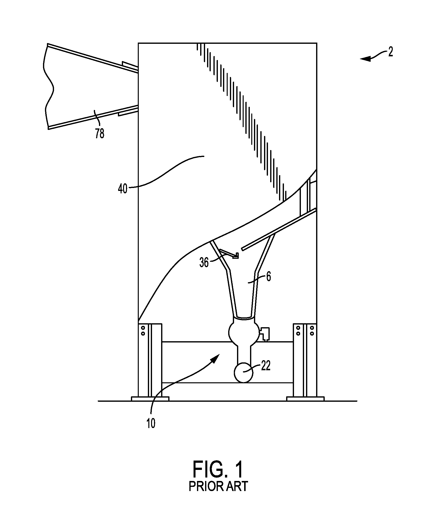
However, indoor gun firing range enclosures present particularly difficult problems for proper ventilation because of the velocity of the bullets and the lead they contain.
Lead-based ammunition, however, can fragment into dust-sized particles upon impact with certain projectile traps, spreading toxic lead vapor and dust.
The concentration of these contaminants must not be allowed to build up in the atmosphere of the shooting range, but due to regulations and general safety concerns, these contaminants cannot be released outside.
Such skidding can strip layers of lead from the surface of the decelerating bullet, resulting in large quantities of fine lead dust.
However, drawing air from the bullet trap and into filters can create further problems.
Bullets ultimately may fragment into many small pieces during deceleration, producing fragments small enough to be carried by strong air flow.
Thus the negative air pressure may unnecessarily pull lead from the trap that would otherwise be removed by a collection system at the bottom of the trap.
Once in the ventilation system, such fragments may become caught in the filters used to trap aerosolized lead or other metals, requiring frequent and costly filter replacement.
These solutions, however, respectively require frequent maintenance, expensive mechanisms, and a great deal of space and periodic cleaning, and do not adequately solve the problem.

Method used


Image

  • Dust containment unit manifold
  • Dust containment unit manifold
  • Dust containment unit manifold

Examples


Embodiment Construction

[0036]Various aspects of the invention and accompanying drawings will now be discussed in reference to the numerals provided therein so as to enable one skilled in the art to practice the present invention. The skilled artisan will understand, however, that the methods described below can be practiced without employing these specific details, or that they can be used for purposes other than those described herein. Indeed, they can be modified and can be used in conjunction with products and techniques known to those of skill in the art in light of the present disclosure. The drawings and the descriptions thereof are intended to be exemplary of various aspects of the invention and are not intended to narrow the scope of the appended claims. Furthermore, it will be appreciated that the drawings may show aspects of the invention in isolation and the elements in one figure may be used in conjunction with elements shown in other figures.

[0037]Reference in the specification to “one embodi...


PUM

PropertyMeasurementUnit
Angleaaaaaaaaaa
Widthaaaaaaaaaa
Areaaaaaaaaaaa

Abstract

A dust containment manifold includes an angled, broadened head with one or more openings through which suction is applied to bullets as they fall from a deceleration chamber or bullet trap. The dust containment manifold may be disposed generally beneath the bullet trap and angled so as to reduce the chance that small fragments will enter the bullet trap ventilation system and become lodged in the ventilation filters.

Description

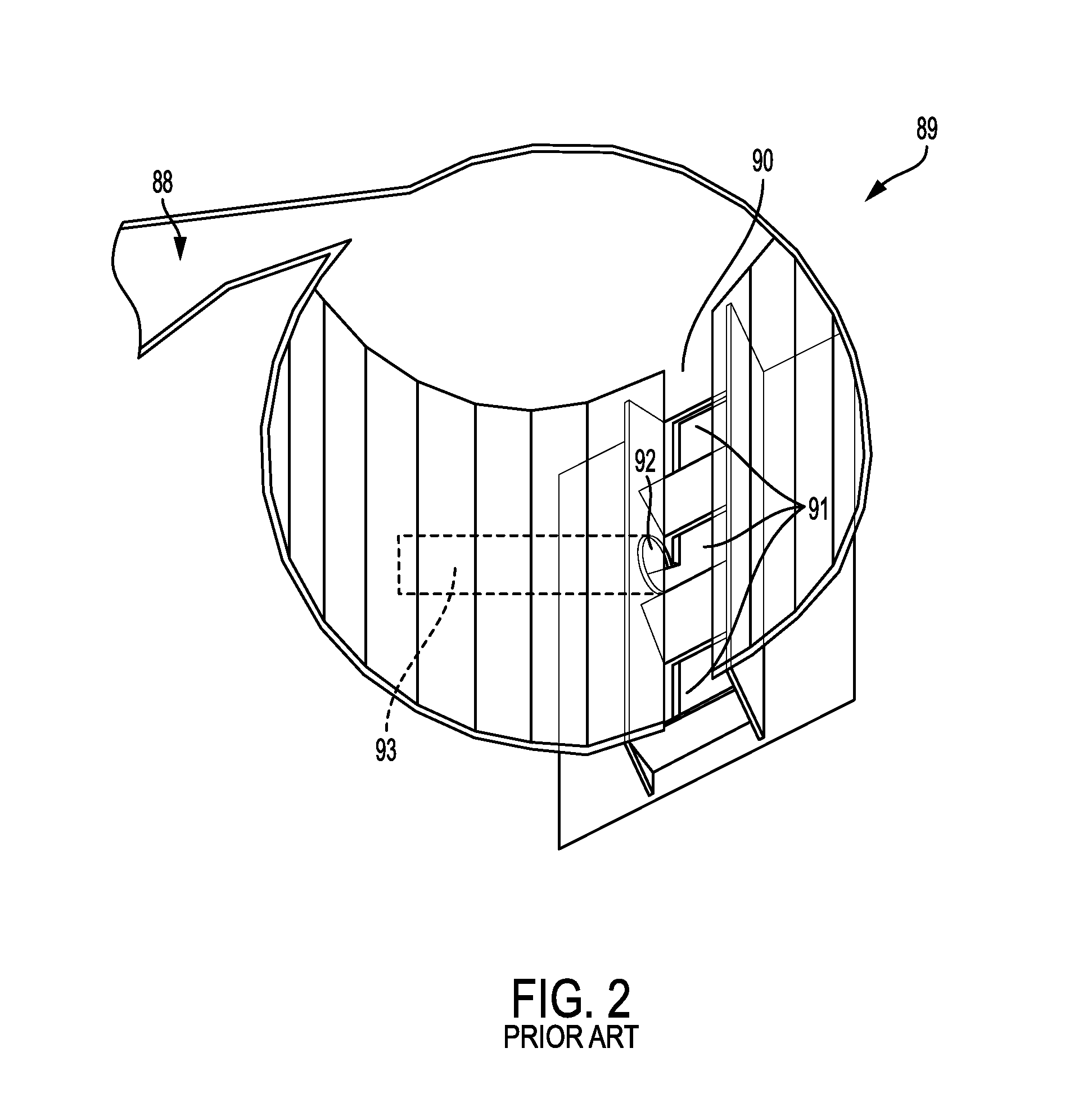
BACKGROUND[0001]1. State of the Art[0002]The present invention relates to ventilation systems used in indoor firing range enclosures for training in the firing of pistols and other firearms. More specifically, the present invention relates to a ventilation port and manifold which prevent bullet fragments from entering the ventilation system, reducing wear on fine particulate filters.[0003]2. Field of Art[0004]In order to maintain proficiency in the use of firearms, it is common for law enforcement officers, members of the military, and sportsmen to engage in target practice to improve or maintain their skills. However, indoor gun firing range enclosures present particularly difficult problems for proper ventilation because of the velocity of the bullets and the lead they contain.[0005]Almost all of America's estimated 10,000 gun ranges permit the firing of lead-based bullets. Lead-based ammunition, however, can fragment into dust-sized particles upon impact with certain projectile t...

Claims


Application Information

Patent Timeline
IPC IPC(8): F24F7/08F24F13/068
CPCF24F13/068F24F7/08F41J13/02A47L5/38A47L9/1625A47L9/165A47L9/1683B01D45/16B03C3/155B08B15/026F41J11/00Y10S55/03
Inventor STOLWORTHY, DEANWALL, DARREN
Owner ACTION TARGET
Learn More