LED Lighting Lamp

a technology of led lighting and diodes, which is applied in the direction of lighting and heating apparatus, semiconductor devices for light sources, and support devices for lighting, etc., can solve the problems of falling, electric shock or fire risk of fluorescent lamps, etc., and achieve the effects of enhancing stability, reducing weight of devices, and preventing electric shock or fire risk

Inactive Publication Date: 2012-04-26
LUMIRICH
View PDF7 Cites 20 Cited by
  • Summary
  • Abstract
  • Description
  • Claims
  • Application Information

AI Technical Summary

Benefits of technology

[0023]According to the present invention, by using a base of R17D Base standard, the pin portion which is an electrode is not exposed to the outside so that electric shock or fire risk can be prevented so as to enhance stability, and damage of a product or fire risk which may occur when an LED lighting lamp of G13 Base is being connected to a ballast stabilizer for a conventional fluorescent lamp of G13 Base can be prevented.
[0024]Furthermore, since a circular light diffusion cover is used, weight of the device can be reduced and breakdown or safety accident due to drop can be prevented.
[0025]Furthermore, since the plurality of the light emitting diode devices are arranged in various angles, angle of light emission can be widened.

Problems solved by technology

A pin portion of G13 Base may be deformed by a long time use, and this may cause a safety problem that the fluorescent lamp may be separated and dropped.
An LED fluorescent lamp may also use G13 Base and thus it is used to be connected to a conventional lamp mount, so if a user may connect the LED fluorescent lamp to a conventional ballast stabilizer, electric shock or fire may occur and this may raise credibility problem of the LED fluorescent lamp.

Method used


Image

  • LED Lighting Lamp
  • LED Lighting Lamp
  • LED Lighting Lamp

Examples


Embodiment Construction

[0034]Embodiments of the present invention will be explained with reference to the accompanied drawings hereinafter.

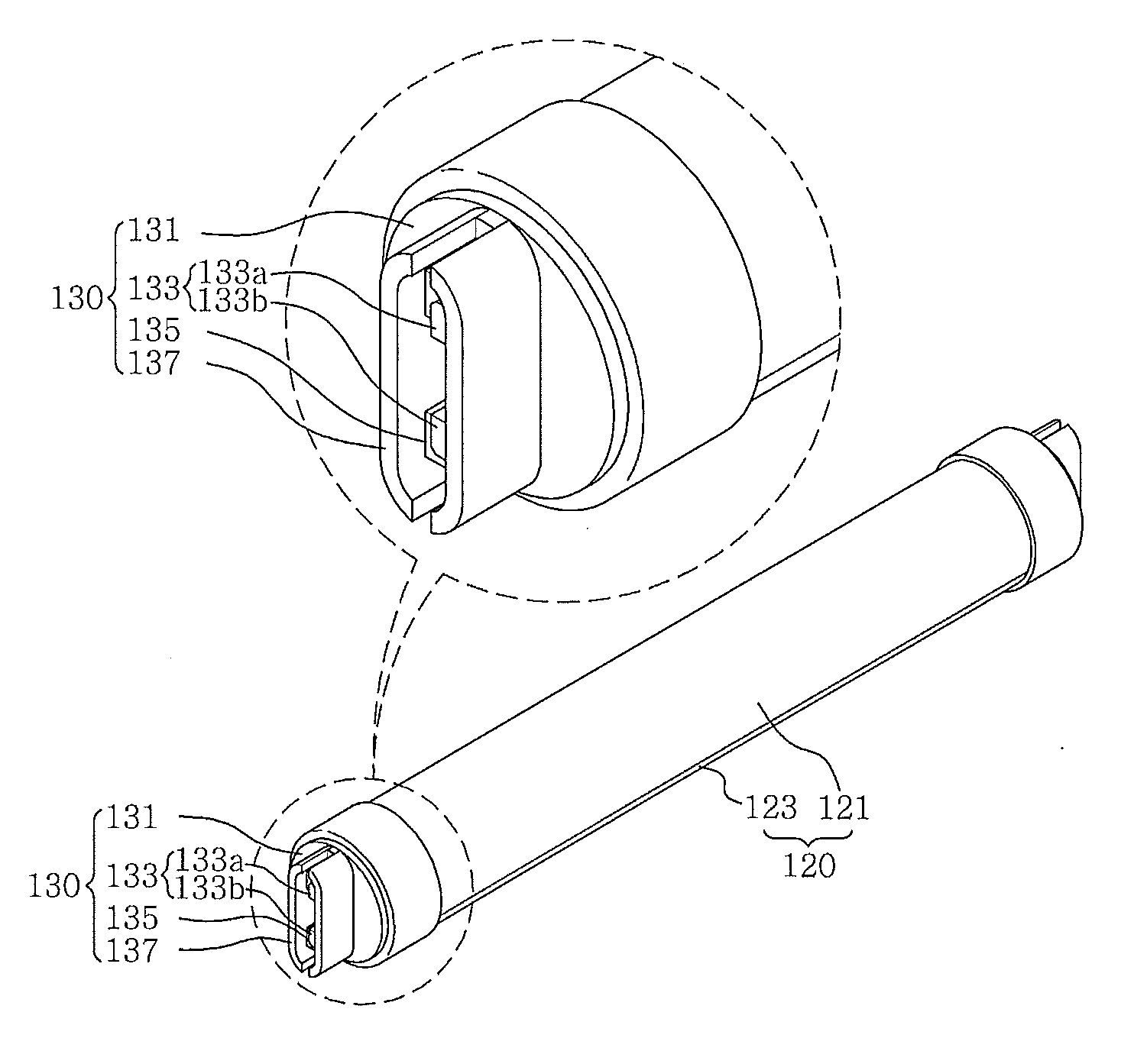
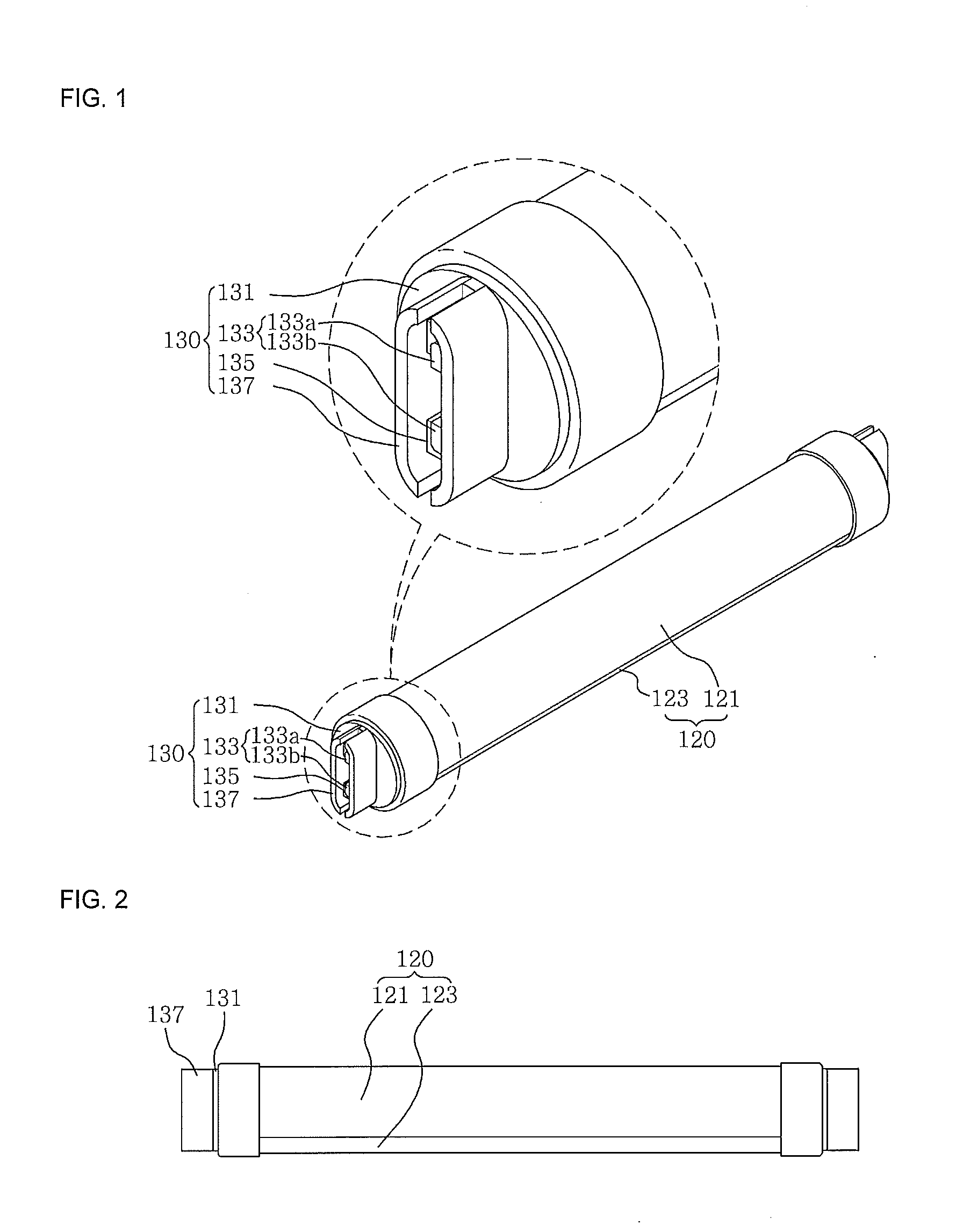
[0035]FIG. 1 is a perspective view of a light emitting diode lighting lamp according to an embodiment of the present invention, and FIG. 2 is a front view of a light emitting diode lighting lamp according to an embodiment of the present invention.

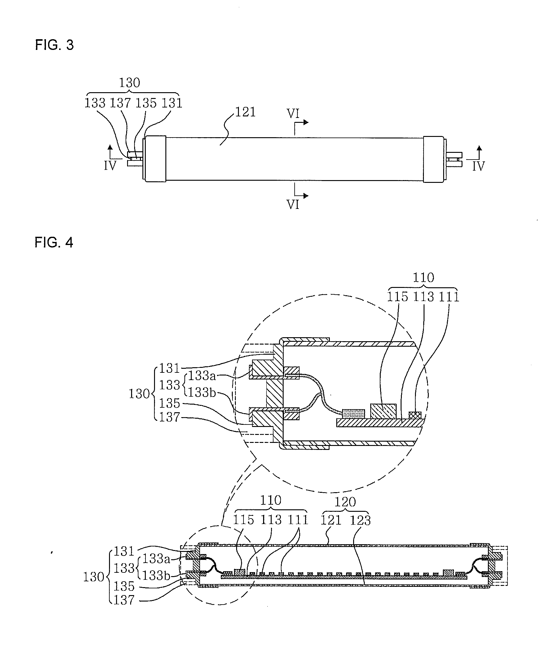
[0036]FIG. 3 is a top view of a light emitting diode lighting lamp according to an embodiment of the present invention, FIG. 4 is a cross sectional view taken along a line IV-IV in FIG. 3, FIG. 5 is a side view of a light emitting diode lighting lamp according to another embodiment of the present invention, and FIG. 6 is a cross sectional view taken along a line VI-VI in FIG. 3.

[0037]Referring to FIG. 1 to FIG. 6, a light emitting diode (LED) lamp 100 according to an embodiment of the present invention includes a light emitting diode (LED) module 100 which includes at least one LED printed circuit board (PCB) 113 and a plurali...


PUM


Abstract

A light emitting diode lighting lamp includes: an LED module having at least one LED PCB and a plurality of LED devices which are disposed on the LED PCB; a cover enclosing the LED module; and a pair of bases which are respectively connected to both ends of the cover. The respective base includes: a cap which coupled to an end of the cover; a pin portion for applying electricity to the LED module; a fixing portion surrounding a lower end of the pin portion to fix the pin portion; and a guard which is formed to be higher than an end of the pin portion and encloses the pin portion along a circumference direction.

Description

CROSS-REFERENCE TO RELATED APPLICATION[0001]This application claims priority to and the benefit of Korean Patent Application No. 10-2010-0030174 filed in the Korean Intellectual Property Office on Apr. 2, 2010, the entire contents of which are incorporated herein by reference.FIELD OF THE INVENTION[0002]The present invention relates to a light emitting diode (LED) lighting lamp.BACKGROUND ART[0003]In case of a conventional fluorescent lamp device, a fluorescent lamp is fitted into a socket having G13 Base of a lamp mount. A pin portion of G13 Base may be deformed by a long time use, and this may cause a safety problem that the fluorescent lamp may be separated and dropped.[0004]An LED fluorescent lamp may also use G13 Base and thus it is used to be connected to a conventional lamp mount, so if a user may connect the LED fluorescent lamp to a conventional ballast stabilizer, electric shock or fire may occur and this may raise credibility problem of the LED fluorescent lamp.[Technical...

Claims


Application Information

Patent Timeline
Patent Type & Authority Applications(United States)
IPC IPC(8): F21V29/00F21V21/00F21V5/00
CPCF21K9/17F21Y2111/005F21Y2103/003F21Y2101/02F21K9/27F21Y2103/10F21Y2107/30F21Y2115/10F21V19/003F21V29/70F21V29/87
Inventor KIM, HA CHUL
Owner LUMIRICH
Why Eureka
Try Eureka