Device for peel test

a peel test and peeling technology, applied in the field of peeling test devices, can solve the problems of change of peel angle, test plate may vibrate violently, difficulty in maintaining peeling angle, etc., and achieve the effect of conducting a peeling test simply and accurately

Active Publication Date: 2012-05-03
KYOWA INTERFACE SCI
View PDF28 Cites 31 Cited by
  • Summary
  • Abstract
  • Description
  • Claims
  • Application Information

AI Technical Summary

Benefits of technology

[0023]The device for peel test according to the present invention achieves an excellent effect as the device is capable of conducting a peel test simply and accurately.

Problems solved by technology

However, the 90-degree peel test has found difficulty in maintaining a peel angle (angle formed between a test plate an adhesive tape sticks to and the adhesive tape being pulled) at 90 degrees all the time during the test.
A peel position moves transversely on the test plate as the adhesive tape is pulled away further, resulting in a problem of change of a peel angle.
The technique of sliding a test plate with a string disclosed in Non-Patent Literature 1 mentioned above may generate a difference between a peel length and a sliding distance of the test plate due to flexure or stretch of the string, leading to a problem as a peel angle is changed during a test.
In particular, a test plate may slide a distance longer than a peel length due to inertial force, or the test plate may vibrate violently if a peel test is conducted at a high speed.
This results in a problem of considerable reduction of measurement accuracy.
This results in a problem of the complex and high-cost structure of a measuring device.

Method used


Image

  • Device for peel test
  • Device for peel test
  • Device for peel test

Examples


Embodiment Construction

[0034]An embodiment of the present invention will now be described below with reference to the accompanying drawings. It should be noted that teeth of gears and racks are not shown in the drawings.

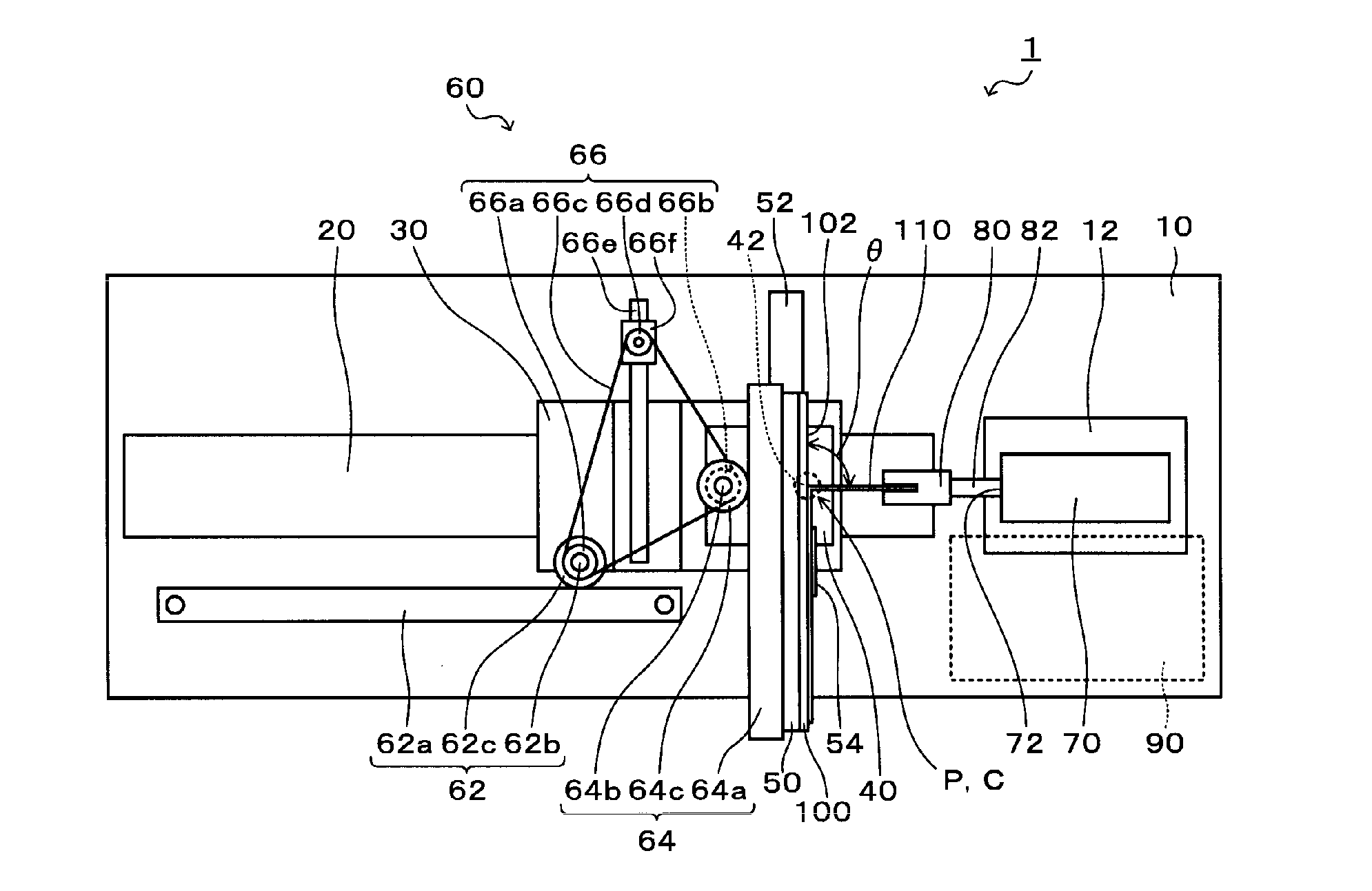
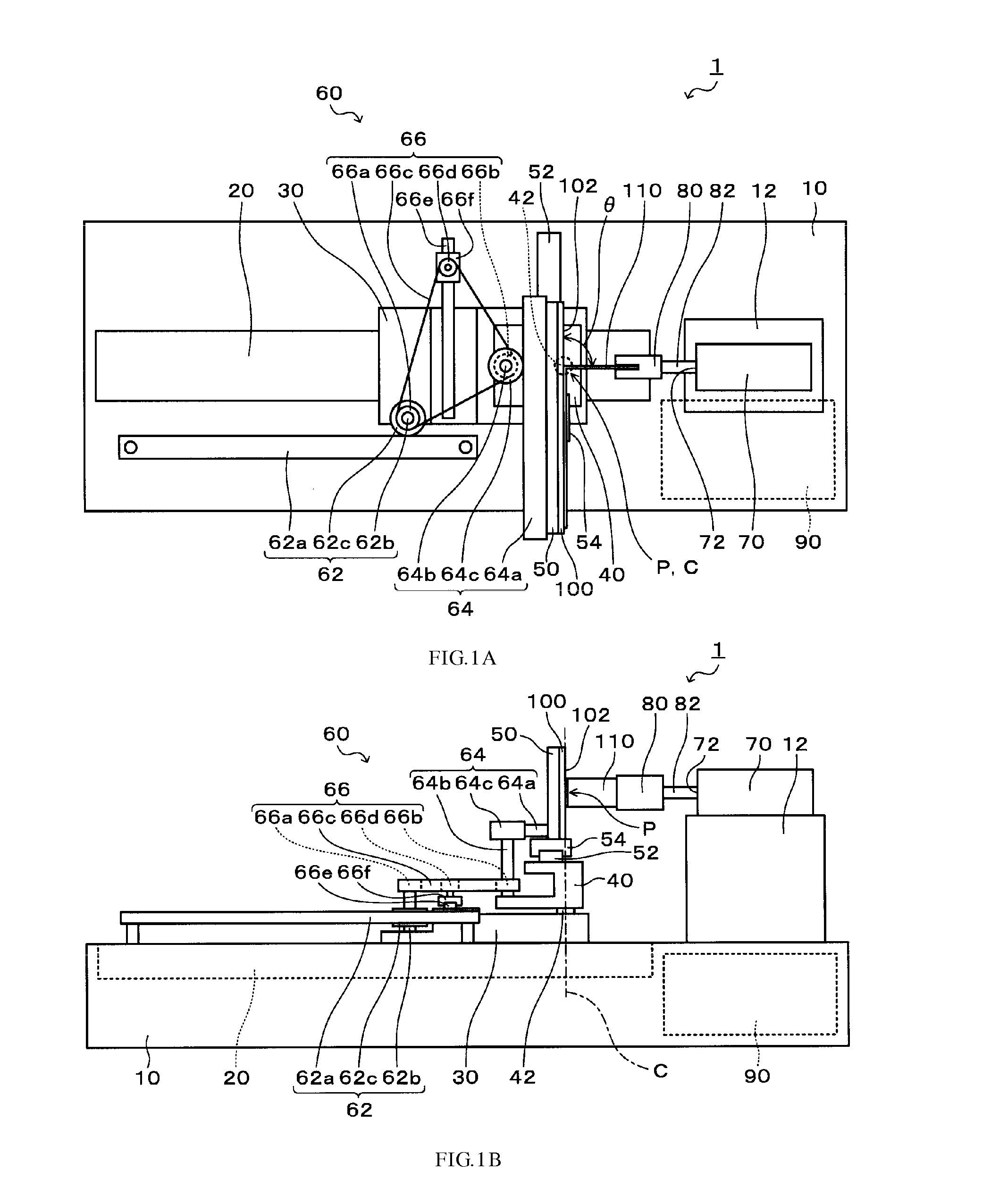
[0035]The structure of a device for peel test (peel testing device) 1 according to the embodiment of the present invention will be described first. FIGS. 1A and 1B are schematic diagrams showing the device for peel test 1 according to the embodiment. FIG. 1A is a plan view of the device 1 for peel test, and FIG. 1B is a front view of the same. The device for peel test 1 of the embodiment is intended to measure a force required for peeling a test film 110 that is, for example, an adhesive tape or a plated coating off a surface of a test object 100 in the form of a flat plate.

[0036]As shown in FIGS. 1A and 1B, the device 1 for peel test includes a base 10, a moving mechanism 20 arranged in an upper part of the base 10, a movable member 30 caused to linearly move by the moving mechanism 20, a...


PUM

PropertyMeasurementUnit
peel angleaaaaaaaaaa
angleaaaaaaaaaa
angleaaaaaaaaaa

Abstract

A device for a peel test. The device includes: a gripping member to grip an end of a test film to be peeled off a test object; a movable member linearly moving in a direction to or away from the gripping member; a holding member for the movable member capable of linearly moving in a direction along a peel surface of the test object while holding the test object; a moving mechanism configured to move the movable member linearly; a load measuring unit configured to measure a load applied to the gripping member; a first conversion mechanism to convert the linear motion of the movable member to rotational power, and output the rotational power; and a second conversion mechanism to convert the rotational power output from the first conversion mechanism to the linear motion of the holding member relative to the movable member.

Description

BACKGROUND OF THE INVENTION[0001]1. Field of the Invention[0002]The present invention relates to a device for peel test used, for example, for testing the adhesive force of adhesive tapes or adhesive sheets, peel strength in the case of two bonded members, and the adhesive force of surface coatings formed by plating or the like.[0003]2. Description of the Related Art[0004]A peel test is a test method conventionally conducted to measure the adhesive force (sticking force) of adhesive tapes or adhesive sheets, and the peel strength of adhesive agents and the like. Examples of the peel test methods include a 90-degree peel test, a 180-degree peel test, a T-peel test, and a peel test with a floating roller. A 90-degree peel test and a 180-degree peel test applied as test methods for adhesive tapes or adhesive sheets are defined, for example, in JIS Z 0237. A 90-degree peel test, a 180-degree peel test, a T-peel test, and a peel test with a floating roller applied as test methods for adh...

Claims


Application Information

Patent Timeline
Patent Type & Authority Applications(United States)
IPC IPC(8): G01N19/04
CPCG01N19/04G01N2203/0605G01N2203/0025
Inventor HOSHINO, YOSHINORI
Owner KYOWA INTERFACE SCI
Why Eureka
Try Eureka