
Dock system

a ladder frame and ladder technology, applied in special-purpose vessels, transportation and packaging, furniture parts, etc., can solve the problems of heavy weight, damage to anyone walking over the dock in their bare feet, and wood may splinter, so as to maintain the transverse and longitudinal stability of the dock

Inactive Publication Date: 2012-05-03
GERST PAUL R +2
View PDF5 Cites 1 Cited by
  • Summary
  • Abstract
  • Description
  • Claims
  • Application Information

AI Technical Summary

Benefits of technology

[0016]The engagement between the cross member connector and the respective cross member may facilitate vertical orientation relative to the upper walking surface of the dock. In other words, the cross member connector may position the cross member for supporting the upper walking surface of the dock.
[0019]The roller assemblies may be connected to the dock for maintaining the transverse and longitudinal stability of the dock.

Problems solved by technology

Although wood is a commonly used construction material, it is very heavy compared to the weight of modern composite material.
Thus, it may be problematic in relation to a floating dock.
In particular, the wood may splinter, which may cause harm to anyone walking over the dock in their bare feet, which tends to occur when someone is swimming off of the dock.
Furthermore, the screws or nails holding the wood together may protrude through the wood, thereby creating a safety hazard.
The screws or nails may also fall out of the wood, which tends to weaken the structural integrity of the dock.
In addition, the wood is liable to further structural weakening caused by termite infestation or rotting of the wood.
An additional drawback with most wood-framed docks is that they are typically custom-built for the specific user.
In this manner, a considerable amount of time is spent designing and constructing the dock, which usually increases the cost thereof.
Although concrete is a regularly used construction material, there may be some drawbacks to using it to construct a floating dock, especially when the dock is used over a body of water having fluctuating water levels (i.e. ocean or reservoir).
Consequently, the dock may be placed under stress, which may cause cracking in the concrete.
If the concrete cracks, salt water may seep into the dock and weaken the structural integrity thereof.
Metallic floating docks are undesirable in saltwater because of corrosion problems.
However, even in freshwater, metal docks may bend when the level of the water decreases to the point that the portions of the dock are resting on the shore, while other portions remain floating (as may be the case in a reservoir).
In rough conditions, waves may cause the dock to rise and fall along the pilings.
However, there is generally a small amount of clearance between the roller and the piling.
Therefore, under rough conditions, the rollers may crash with the pilings, which typically results in banging and instability of the dock.

Method used


Image

  • Dock system
  • Dock system
  • Dock system

Examples


Embodiment Construction

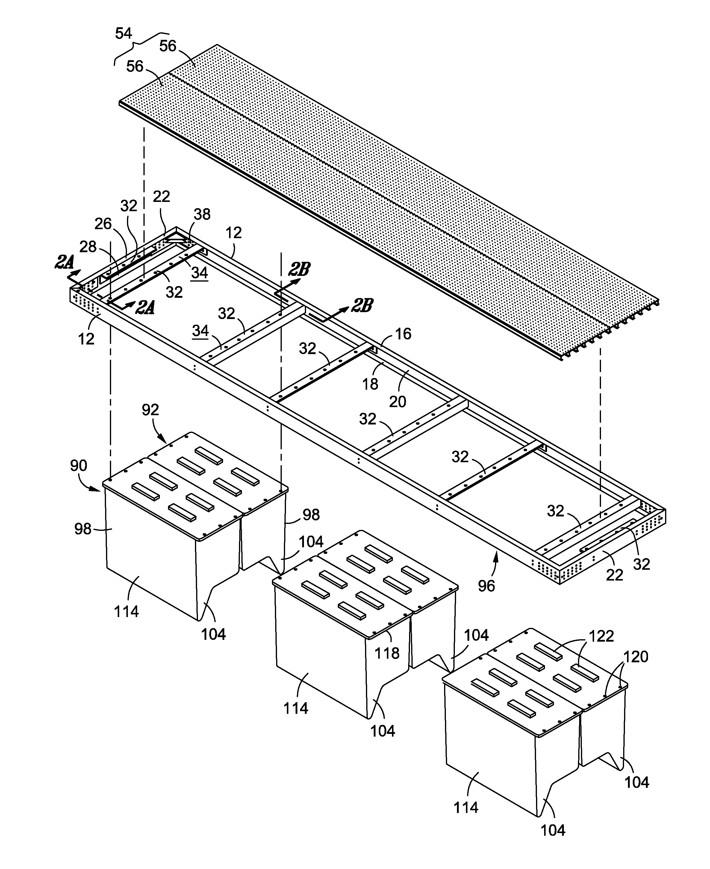
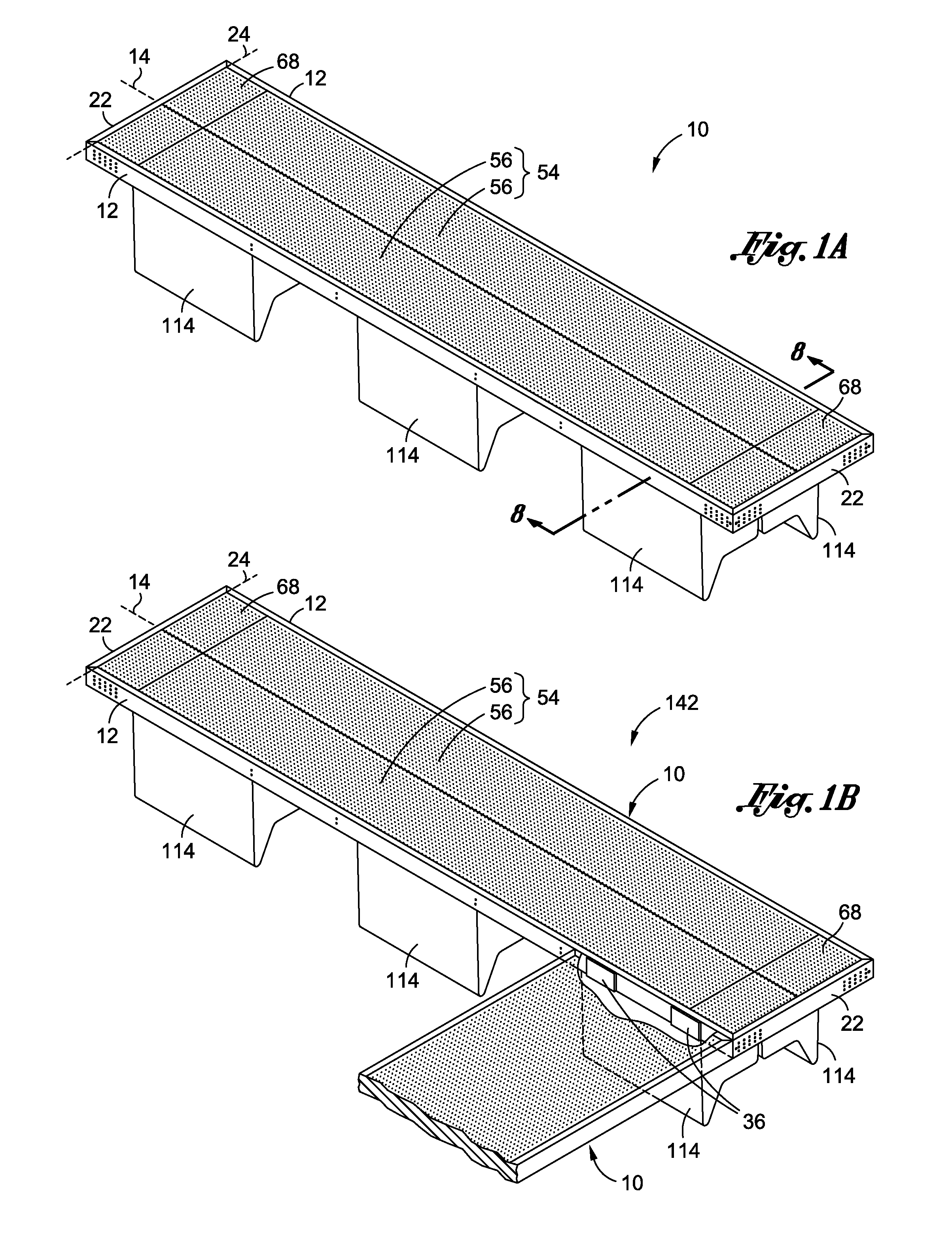
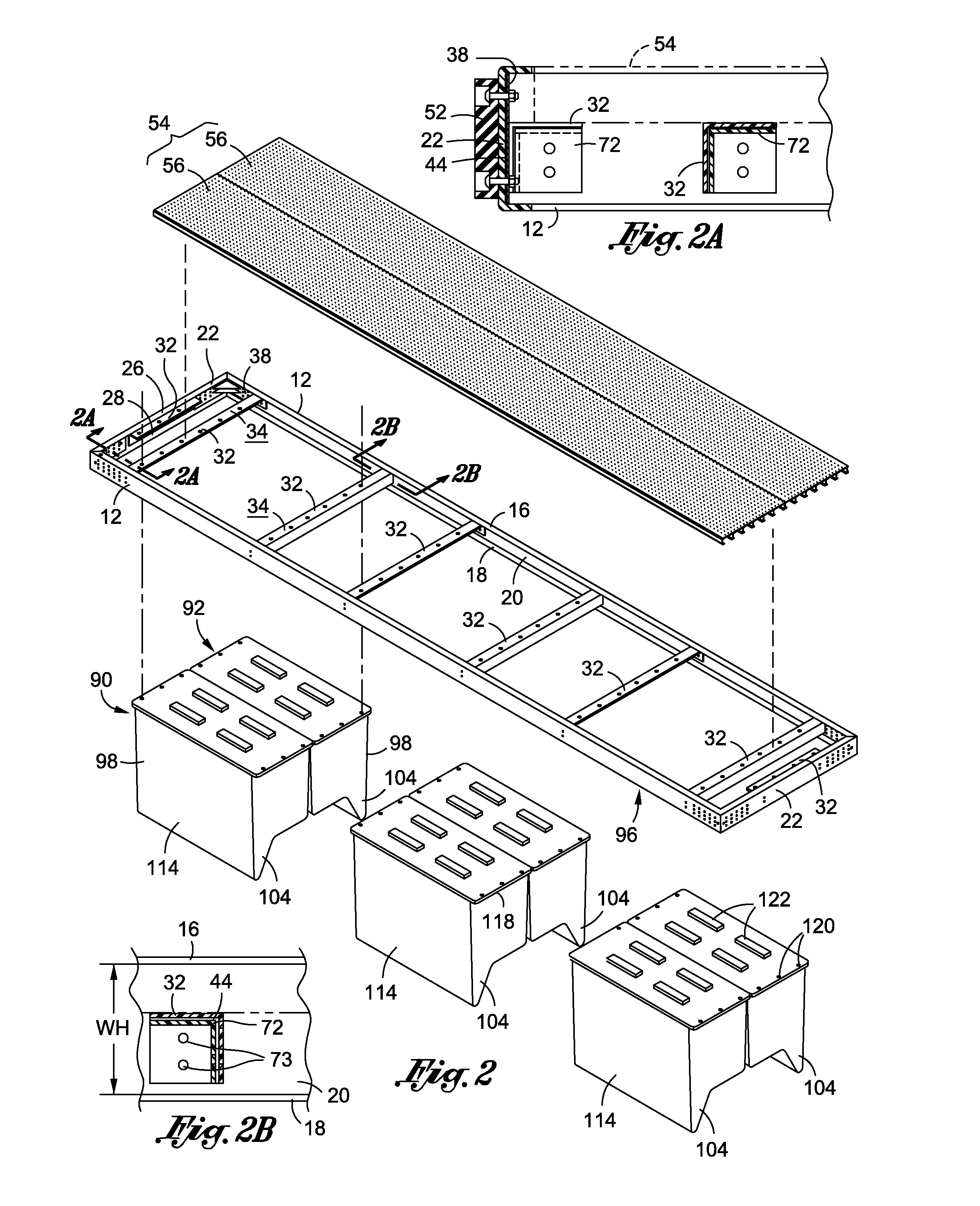
[0061]Referring now to the drawings where the showings are for purposes of illustrating a preferred embodiment of the present invention only, and not for purposes of limiting the same, there is shown a dock 10 constructed in accordance with an embodiment of the present invention. According to various embodiments of the present invention, the dock 10 includes a frame formed out of a pultruded material to provide a generally stronger and more durable dock 10 relative to existing docks.

[0062]Referring now to FIGS. 1-3, the dock 10 includes a pair of primary frame members 12 extending along a length thereof. According to one implementation, each primary frame member 12 includes a primary upper flange 16, a primary lower flange 18, and a primary wall 20 extending between the primary upper and lower flanges 16, 18. The primary wall 20 defines a wall height “WH” (See FIG. 2B) extending from the primary upper flange 16 to the primary lower flange 18. The primary frame members 12 extend alon...


PUM


Abstract

There is provided a dock having a pair of primary frame members and a pair of secondary frame members. A plurality of cross members extends between the pair of primary frame members. The dock includes a plurality of cross member connectors for connecting the cross members to the primary frame members. Each cross member connector includes a frame contact portion and a cross member engagement portion extending from the frame contact portion. The frame contact portion is connected to a respective one of the plurality of primary frame members. The cross member engagement portion defines a channel sized and configured to receive the alignment plate of a respective one of the plurality of cross members. A roller assembly may also be included for stabilizing the dock relative to an adjacent piling.

Description

CROSS-REFERENCE TO RELATED APPLICATIONS[0001]This application is a continuation-in-part patent application of prior U.S. patent application Ser. No. 12 / 146,326, filed Jun. 25, 2008.STATEMENT RE: FEDERALLY SPONSORED RESEARCH / DEVELOPMENT[0002]Not ApplicableBACKGROUND[0003]1. Field of the Invention[0004]The present invention relates generally to a lightweight and durable ladder framed, skin-stressed structure typically formed of pultruded fiberglass materials joined with adhesives. The particular embodiments discussed herein are floating docks with a gangway leading from the shore or a pier. The floating portion of the system may be stabilized through the use of a piling stabilizing device and pontoons capable of improving the metacenter of the floating system which may enhance the utility of the subject dock, gangway, and pier embodiments of the subject ladder frame structure.[0005]2. Description of the Prior Art[0006]It is well-known that docks are man-made structures that extend fro...

Claims


Application Information

Patent Timeline
Patent Type & Authority Applications(United States)
IPC IPC(8): B63B35/44A47B96/14
CPCB63B35/38
Inventor GERST, PAUL R.GERST, PAUL VERNONGERST, JOHN WILLIAM
Owner GERST PAUL R
Learn More