Aircraft cable routing harness

a technology for aircraft and cable, applied in the direction of conductors, wings, aircraft floors, etc., can solve the problems of increasing aircraft weight, affecting the flight of aircraft, and friction between adjacent cables, so as to avoid the use of complex clips and channel section raceways

Inactive Publication Date: 2012-05-03
AIRBUS OPERATIONS LTD
View PDF7 Cites 62 Cited by
  • Summary
  • Abstract
  • Description
  • Claims
  • Application Information

AI Technical Summary

Benefits of technology

[0009]By providing a harness having an embedded conductor, the use of complex clips and channel section raceways is thereby av

Problems solved by technology

A problem with known raceways is that they add significant weight to the aircraft.
Furthermore, the cables are relatively free to move within the raceways which may affect their proximity (i.e. potentially causing problems with electro-magnetic interference) and may cause friction between a

Method used


Image

  • Aircraft cable routing harness
  • Aircraft cable routing harness
  • Aircraft cable routing harness

Examples


Embodiment Construction

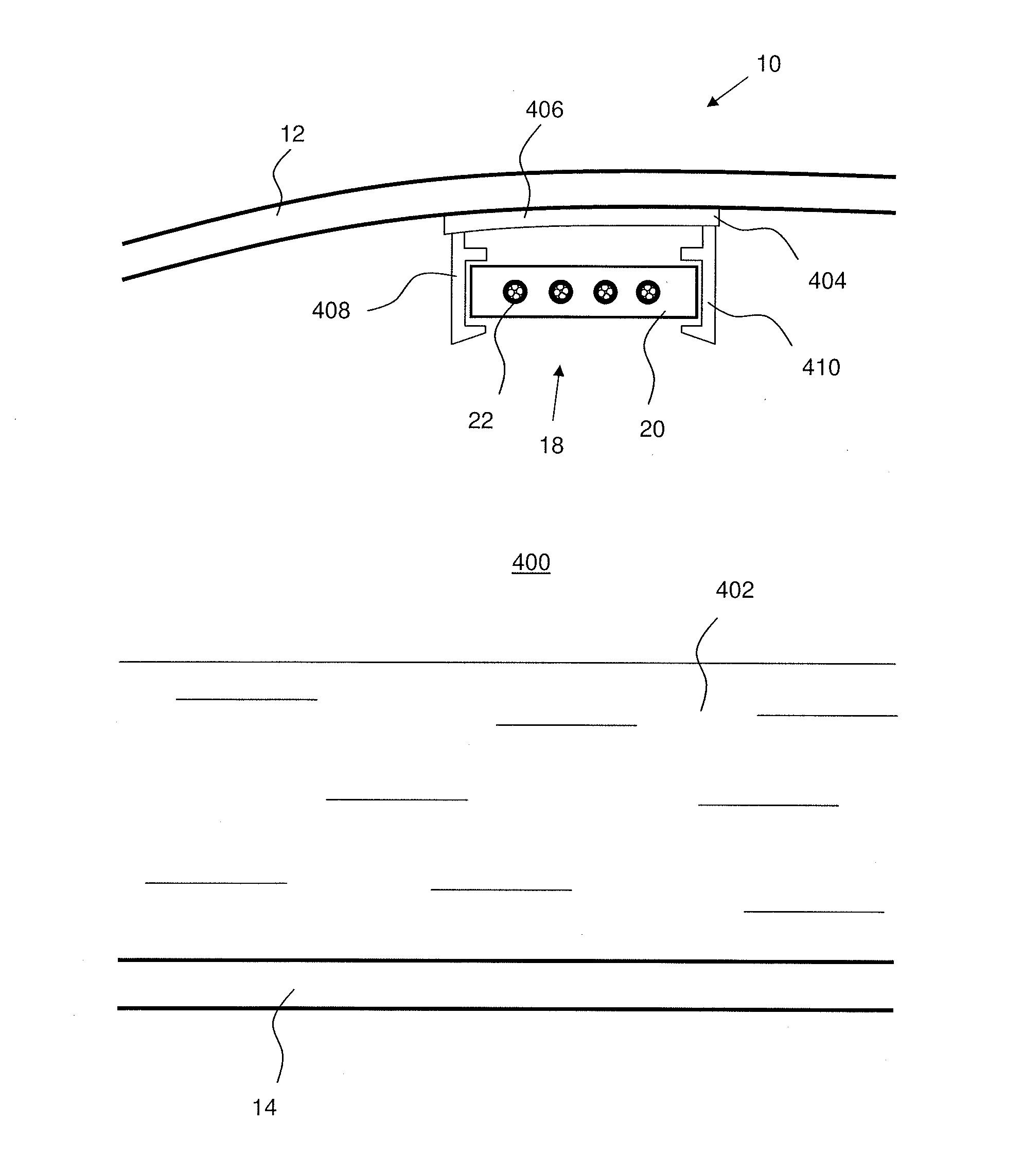
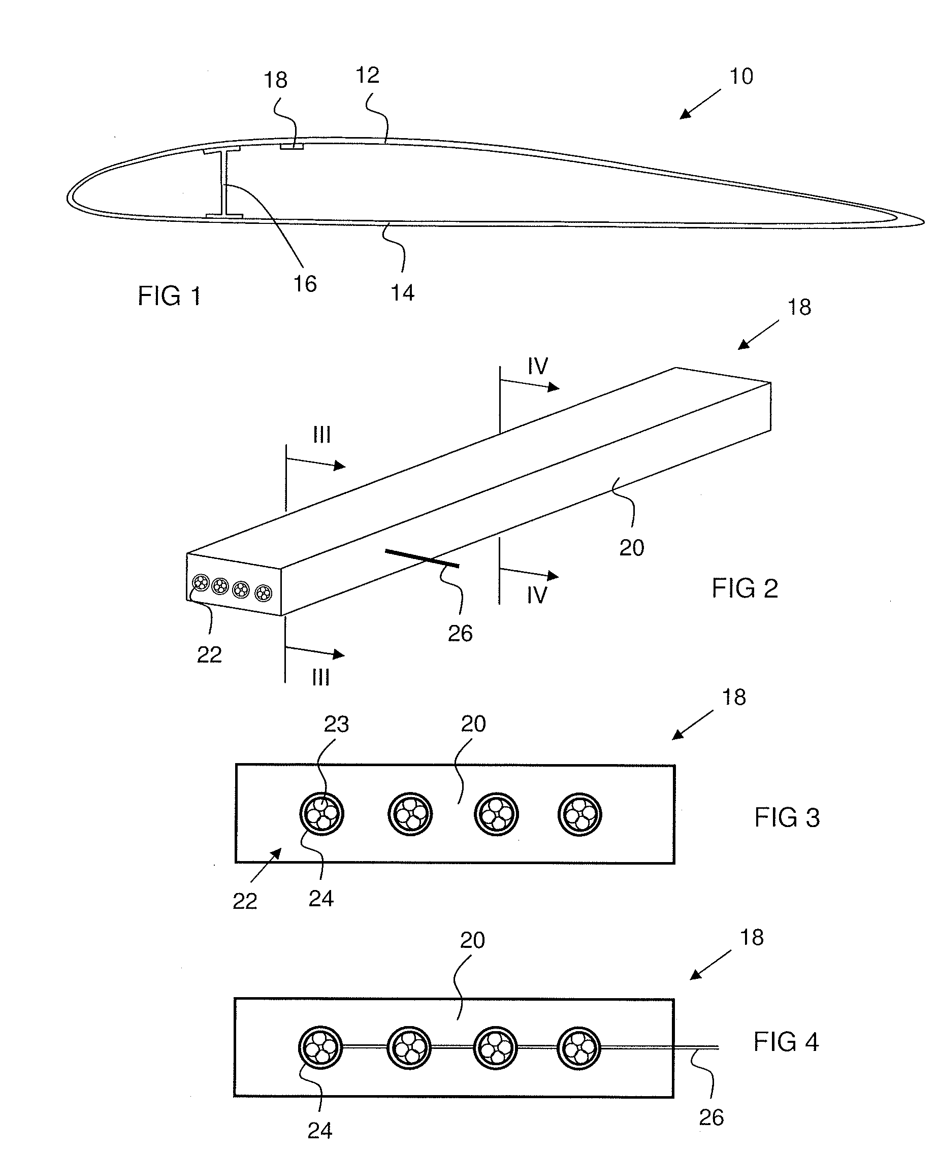
[0033]Referring to FIG. 1, a side cross-section of an aircraft wing 10 is shown having an upper skin 12 and a lower skin 14, a spar 16 and a harness 18. The spar 16 provides structural reinforcement for the wing across its span.

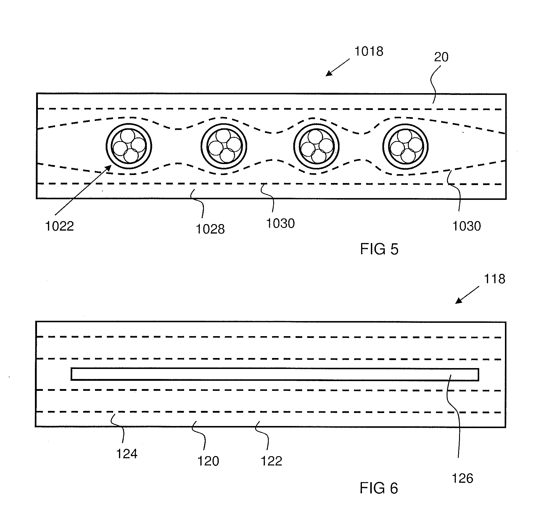
[0034]Referring to FIG. 2, the harness 18 is shown in detail. The harness 18 comprises a body 20 being substantially rectangular in cross-section and being constructed from a glass fibre reinforced polymer (GFRP) material. The body 20 defines four cable groups 22 embedded therein and running substantially along the length of the body 20.

[0035]Referring to FIG. 3, each cable group 22 comprises a plurality of cables 23 in a bundle surrounded by a conductive foil sheath 24. The foil sheath 24 surrounds the bundle of cables 23 and acts as an electro-magnetic shield. Referring to FIG. 4, at positions along the length of the harness 18 (preferably at the ends of the harness) the sheaths 24 break out of the body 20 and are bonded to an earth terminal 26 which is con...


PUM


Abstract

A harness is provided comprising a body having a series of electrical conductors embedded therein and substantially running along the length thereof. The body may be part of a structural component such as stringer.

Description

FIELD OF THE INVENTION[0001]The present invention relates to an aircraft cable routing harness. More specifically, the present invention relates to a cable routing harness having a conductor embedded therein, wherein the harness is a substantially inflexible structural member and may be used in a fuel quantity installation of an aircraft.BACKGROUND OF THE INVENTION[0002]Traditionally, cables are routed throughout aircraft and in particularly through aircraft wings using cable raceways. These raceways are generally constructed from aluminium and comprise channel sections into which cables can be secured. Such cables are often braided to provide electro-magnetic protection. The raceway serves to guide and secure the cables and protect them from external mechanical damage. The cables are often secured in place in the raceway channels using clips.[0003]Fuel quantity installation (FQI) cable harnesses are routed through aircraft fuel tanks, in particular through the tanks in aircraft win...

Claims


Application Information

Patent Timeline
IPC IPC(8): H02G3/02B64D37/06B64C3/18
CPCH02G3/0431B64C3/18
Inventor BLANCHARD, JACKBRYANT, ANTHONY
Owner AIRBUS OPERATIONS LTD
Why Eureka
Try Eureka