Organic light-emitting element, organic light-emitting device, organic display panel, organic display device, and method of manufacturing an organic light-emitting element

Active Publication Date: 2012-05-03
JOLED INC
View PDF3 Cites 24 Cited by
  • Summary
  • Abstract
  • Description
  • Claims
  • Application Information

AI Technical Summary

Benefits of technology

[0007]It is therefore an object of the present invention to provide an organic light-emitting element, an organic light-emitting device, an organic display panel, an organic display device, and a method of manufacturing organic light-emitting elements that improve the light-extraction efficiency of blue light.
[0009]In an organic light-emitting element according to an aspect of the present invention, the physical thickness of the first functional layer is appropriately adjusted so that an interference effect between light that is emitted from the organic light-emitting layer and travels directly towards the second electrode and light that is emitted from the organic light-emitting layer and is reflected by the first electrode before traveling towards the second electrode strengthens blue light. Furthermore, the physical thickness of the second electrode and the difference in refractive index between the second electrode and the layer adjacent thereto are appropriately adjusted so that multiple reflections within the second electrode further strengthen blue light. These multiplicative effects greatly increase the light-extraction efficiency of blue light.

Problems solved by technology

There is still room for improvement of the organic light-emitting element, however, as the light-extraction efficiency of blue light still cannot be considered sufficient as compared to the light-extraction efficiency of green or red light.

Method used


Image

  • Organic light-emitting element, organic light-emitting device, organic display panel, organic display device, and method of manufacturing an organic light-emitting element
  • Organic light-emitting element, organic light-emitting device, organic display panel, organic display device, and method of manufacturing an organic light-emitting element
  • Organic light-emitting element, organic light-emitting device, organic display panel, organic display device, and method of manufacturing an organic light-emitting element

Examples


Embodiment Construction

[Process by Which an Aspect of the Present Invention was Achieved]

[0029]Before concretely describing aspects of the present invention, the following describes the process by which the aspects of the present invention were achieved.

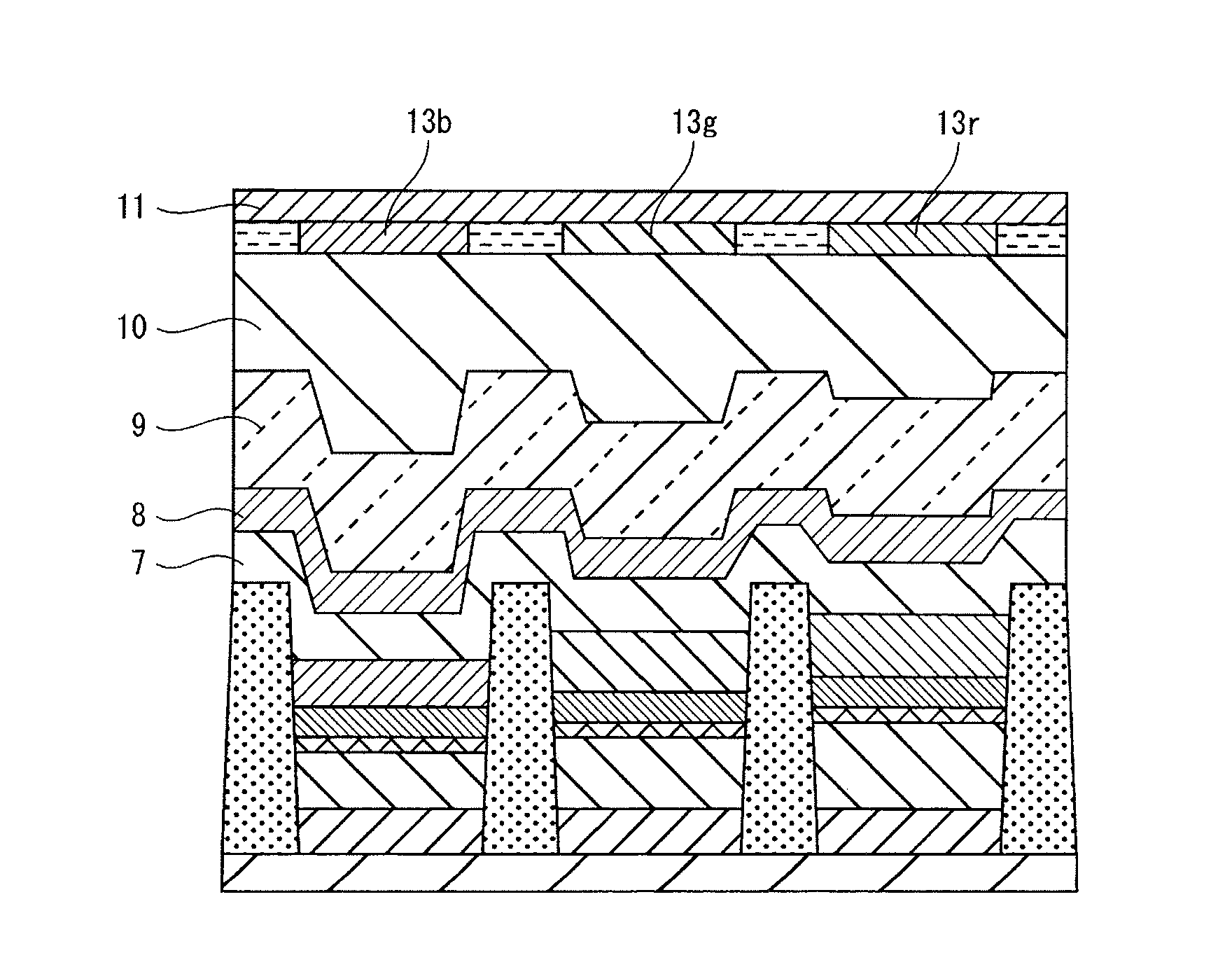
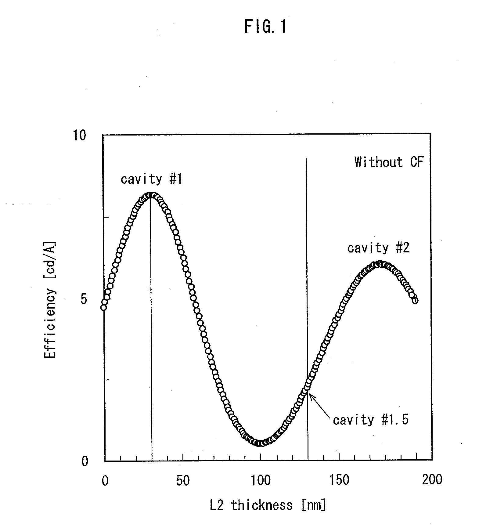
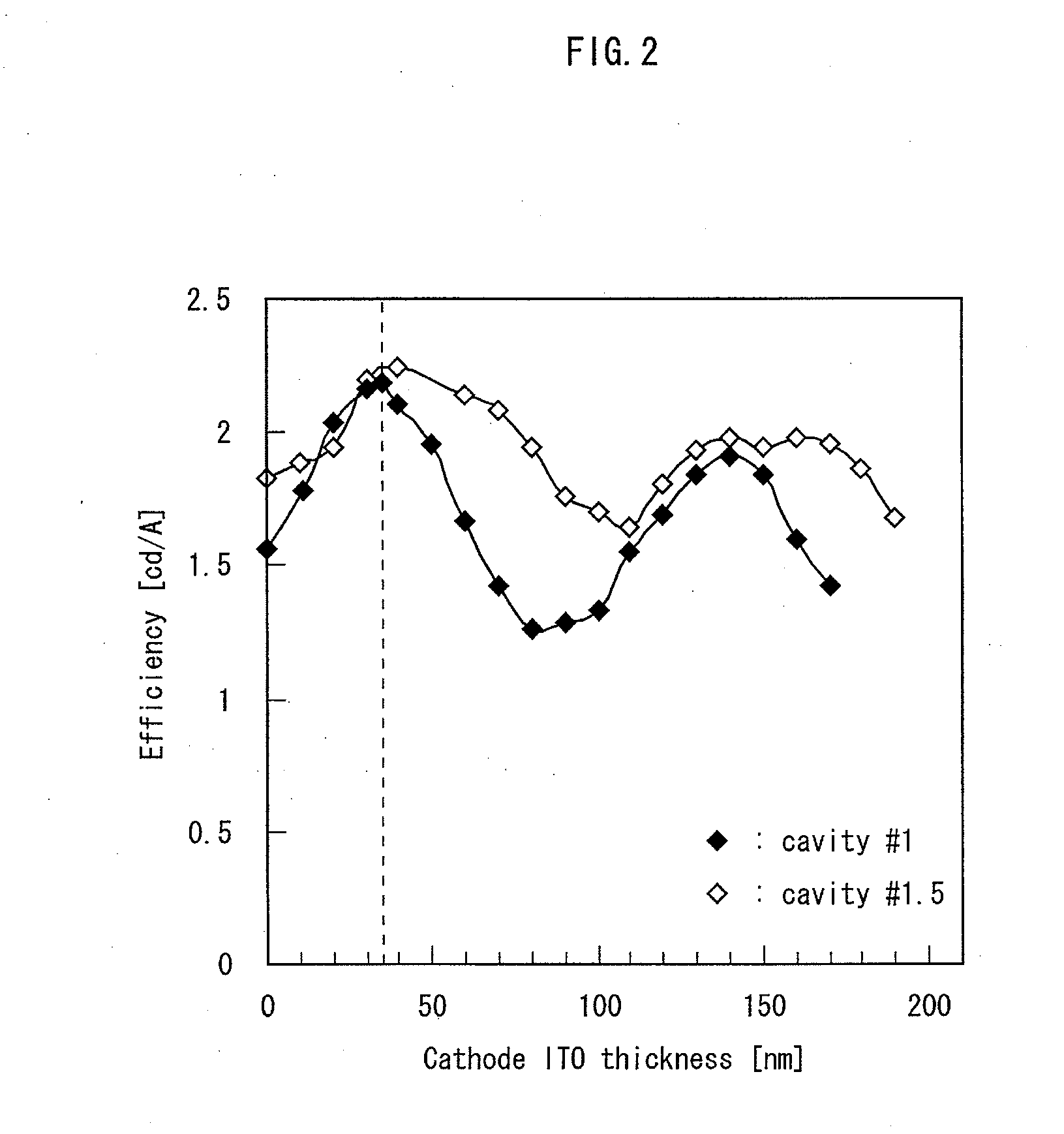
[0030]First, in order to increase light-extraction efficiency, the inventors adopted a resonator (cavity) structure for the organic light-emitting element. Specifically, for an organic light-emitting element in which a reflecting anode, a transparent conductive layer, a hole injection layer, a hole transport layer, an organic light-emitting layer, an electron transport layer, an electron injection layer, and a transparent cathode are layered on a substrate, the inventors adjusted the physical thickness of a functional layer (i.e. the transparent conductive layer, the hole injection layer, and the hole transport layer) disposed between the reflective anode and the organic light-emitting layer in order to strengthen light via the phenomenon of interference.

[...


PUM


Abstract

An organic light-emitting element includes a reflective anode, a first functional layer, an organic light-emitting layer that emits blue light, a second functional layer, a transparent cathode, and a coating layer. An optical thickness of the first functional layer is greater than 0 nm but not greater than 316 nm. A difference in refractive index between the transparent cathode and either a layer adjacent to the transparent cathode within the second functional layer or a layer adjacent to the transparent cathode within the coating layer is from 0.1 to 0.7 inclusive. The transparent cathode has a physical thickness greater than 0 nm but not greater than 70 nm, a refractive index from 2.0 to 2.4 inclusive, and an optical thickness greater than 0 nm but not greater than 168 nm.

Description

[0001]This is a continuation of International Application PCT / JP2010 / 005028, with an international filing date of Aug. 10, 2010.TECHNICAL FIELD [0002]The present invention relates to organic light-emitting elements that rely on the phenomenon of electroluminescence of organic material and in particular to optical design of organic light-emitting elements.BACKGROUND ART[0003]In recent years, use of organic Electro Luminescence (EL) panels that rely on the phenomenon of electroluminescence of organic material has been proposed for display panels used in display devices such as digital televisions. A matrix of red, green, and blue organic light-emitting elements is arranged in an organic EL panel.[0004]It is important to improve light-extraction efficiency of the light-emitting elements, for example from the standpoint of reducing power consumption or increasing service life of the organic EL panel. To this end, Patent Literature 1 proposes technology for increasing light-extraction ef...

Claims


Application Information

Patent Timeline
IPC IPC(8): H01L51/52H01L51/56H01L27/32
CPCH01L51/5234H05B33/28H01L51/5265H10K59/35H10K50/828H10K50/852H10K10/46
Inventor KURATA, KEIKOMATSUSUE, NORIYUKIYONEDA, KAZUHIRO
Owner JOLED INC
Why Eureka
Try Eureka