Excitation circuit for DC sensors

a dc sensor and circuit technology, applied in the direction of resistance/reactance/impedence, instruments, measurement devices, etc., can solve the problems of harmful to the operation of the sensor, voltage drops,

Active Publication Date: 2012-05-03
SAFRAN ELECTRONICS & DEFENSE
View PDF1 Cites 9 Cited by
  • Summary
  • Abstract
  • Description
  • Claims
  • Application Information

AI Technical Summary

Benefits of technology

[0006]An object of the invention is to provide simple means enabling failures in an excitation circuit to be detected and identified.
[0008]Analyzing the signals from the monitoring system and from the regulation system makes it possible to reveal failures and to identify them. The sinewave does not disturb the operation of the sensor which is excited in differential mode, but serves to detect and identify failures. Thus, the monitoring system serves to verify the operation of the amplifiers by detecting their output signals, which signals are AC in normal operation and DC in the event of failure. The regulation system also serves to detect and identify failures. Thus, in normal operation, the regulation system sees only a DC signal, but in the event of one of the amplified paths being short-circuited to ground, the sinewave disappears from that amplified path, while remaining on the other amplified path, such that the sinewave appears in the regulation system. The regulation system also makes it possible to detect the presence of an open circuit (current is then zero) or a differential short circuit (voltage is then zero). Failures are thus detected with components that are simple. The digital regulation also makes it possible to have impedances between the digital controller and the sensor, thereby protecting the digital controller from lightning without having recourse to specific lightning arrestor devices, such as those of the Transorb type, whereas with conventional analog regulation, the presence of such impedances would lead to voltage drops that are harmful to the operation of the sensor and would therefore make it necessary to have recourse to specific lightning arrestor devices.

Problems solved by technology

The digital regulation also makes it possible to have impedances between the digital controller and the sensor, thereby protecting the digital controller from lightning without having recourse to specific lightning arrestor devices, such as those of the Transorb type, whereas with conventional analog regulation, the presence of such impedances would lead to voltage drops that are harmful to the operation of the sensor and would therefore make it necessary to have recourse to specific lightning arrestor devices.

Method used


Image

  • Excitation circuit for DC sensors
  • Excitation circuit for DC sensors

Examples


Embodiment Construction

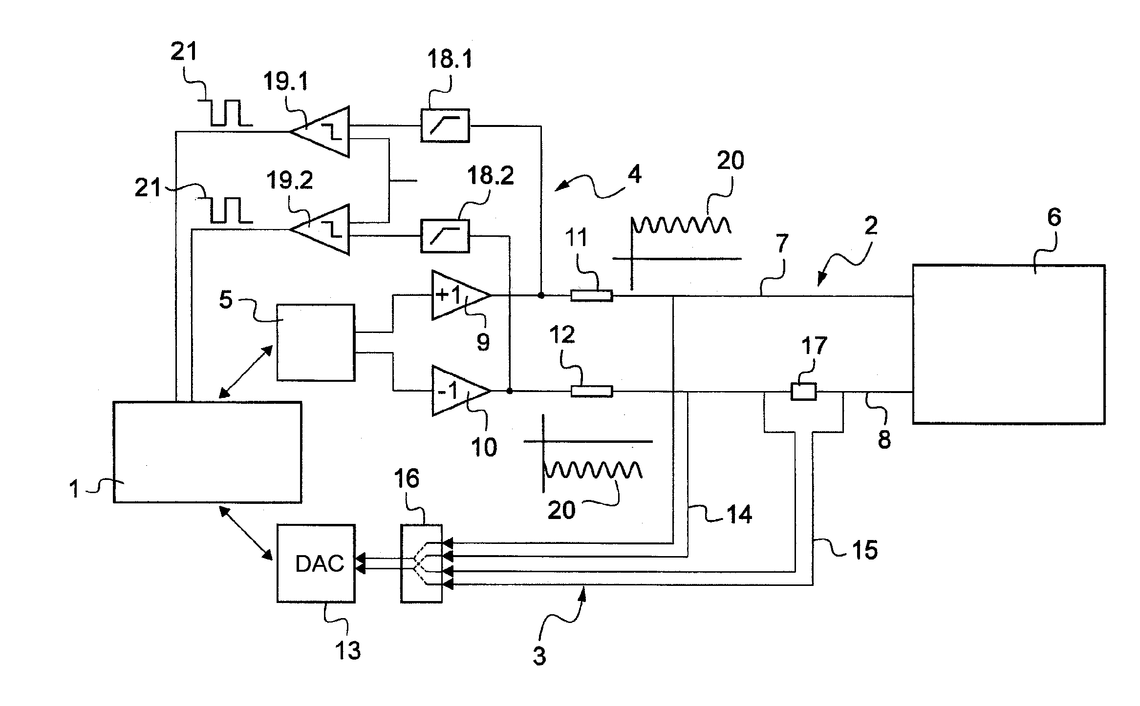
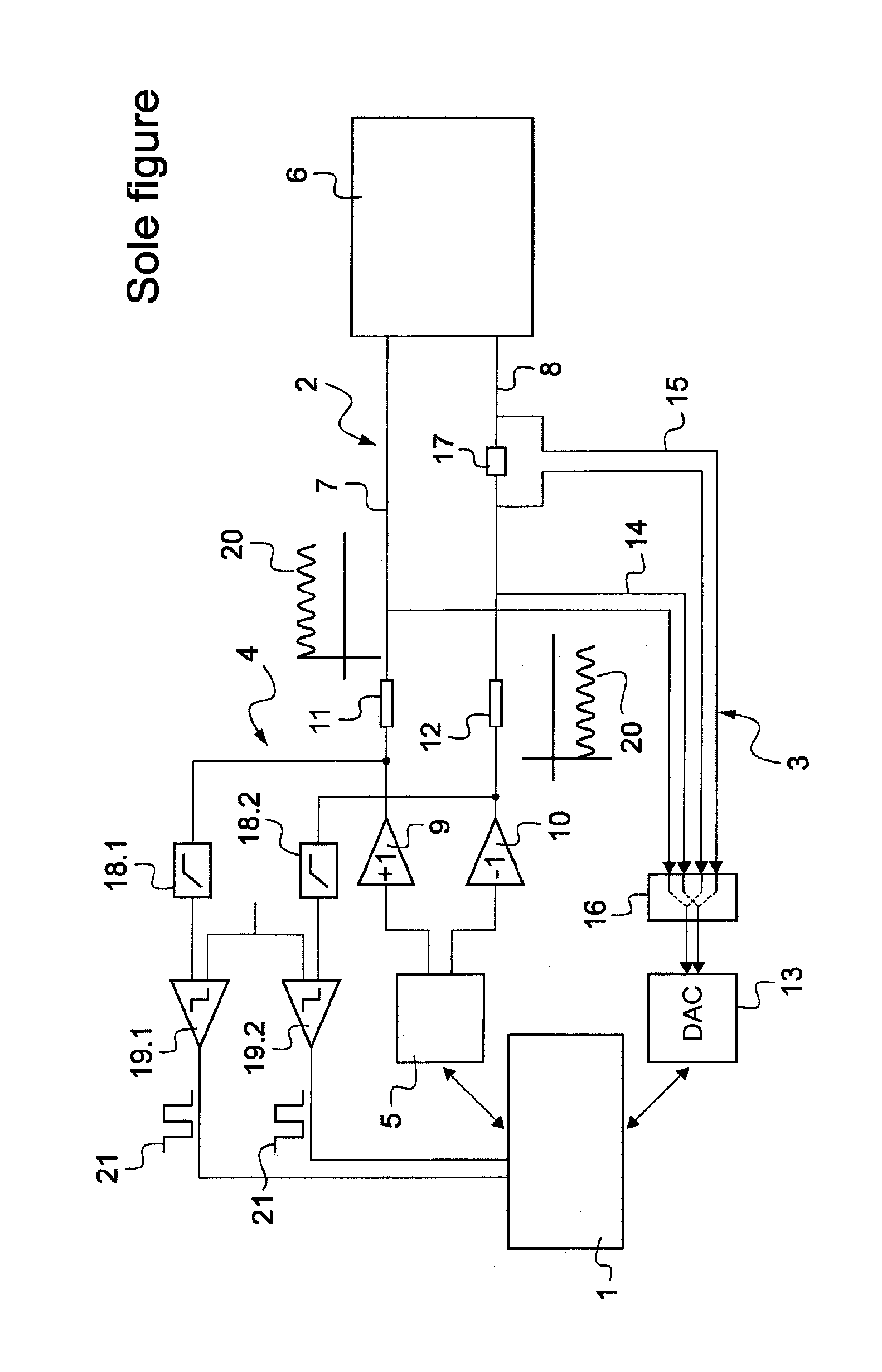
[0013]The excitation circuit in accordance with the invention is intended more particularly for use in a device for controlling an aircraft engine on the basis of information coming from sensors incorporated in the engine and instructions from the pilot of the aircraft. The control device actuates a member for adjusting the rate at which fuel is introduced into the combustion chamber of the engine.

[0014]Such sensors include DC sensors that can be excited either at constant voltage, such as pressure sensors (such as voltage-excited strain gauges), or at constant current such as temperature sensors (such as current-excited platinum probes). The excitation circuit in the preferred embodiment of the invention is arranged to be equally capable of exciting sensors of either of those types.

[0015]The excitation circuit includes a digital regulation calculator 1 (or digital core) connected to a main system, to a regulation loop, and to a monitoring system, given respective overall references...


PUM


Abstract

A circuit for exciting at least one DC sensor is provided in which the circuit has a digital regulation controller connected to a main system and to a regulation loop. The main system has a DAC connected to the sensor via a non-inverted amplified path and via an inverted amplified path in order to send sensor excitation signals including a DC component in differential mode. The regulation system includes an ADC connected to the amplified paths. The circuit includes a monitoring system that is connected to the controller in parallel with the converter in order to send signals as a function of an AC component of the signals taken from the amplified paths. The digital controller is arranged to inject a sinewave in common mode into the excitation signals and to analyze signals output by the monitoring system and signals output by the ADC.

Description

FIELD OF THE INVENTION[0001]The present invention relates to a circuit for exciting direct current (DC) sensors. The excitation circuit is more particularly intended for incorporating in a device for controlling an aircraft engine.BACKGROUND OF THE INVENTION[0002]Such a control device includes a controller that determines in particular the flow rate of fuel as a function of the temperature of the engine, of pressures in the engine, and of the states of various engine components. For this purpose, the device includes excitation circuits and acquisition circuits that are connected to sensors including DC sensors such as thermocouple type temperature probes and strain gauges, that return respective DC signals of small amplitude.[0003]In such an application, where a failure of the control device can have dramatic consequences for the operation of the aircraft, one of the main concerns is to detect faults and preferably to identify the faulty components.[0004]At present, in the absence o...

Claims


Application Information

Patent Timeline
Patent Type & Authority Applications(United States)
IPC IPC(8): G01R27/02G01R31/50
CPCG01D18/00G01R31/025G01R31/08G01R31/50
Inventor GENESTE, NICOLASESTEVE, GWENAEL
Owner SAFRAN ELECTRONICS & DEFENSE
Why Eureka
Try Eureka