Automated emergency power supply system (EPSS) test reporting criticality of epss test failure

a power supply system and automatic technology, applied in power supply testing, instruments, measurement devices, etc., can solve the problems of insufficient monitoring of the terminal voltage of the battery, inability to detect manual data collection methods, subtle and gradual, etc., to increase the overall reliability of the eps system, reduce the burden of staff, and increase reliability

a power supply system and automatic technology, applied in power supply testing, instruments, measurement devices, etc., can solve the problems of insufficient monitoring of the terminal voltage of the battery, inability to detect manual data collection methods, subtle and gradual, etc., to increase the overall reliability of the eps system, reduce the burden of staff, and increase reliability

US20120105097A1Active Publication Date: 2012-05-03SCHNEIDER ELECTRIC USA INC

Image

  • Automated emergency power supply system (EPSS) test reporting criticality of epss test failure
  • Automated emergency power supply system (EPSS) test reporting criticality of epss test failure
  • Automated emergency power supply system (EPSS) test reporting criticality of epss test failure

Examples


Embodiment Construction

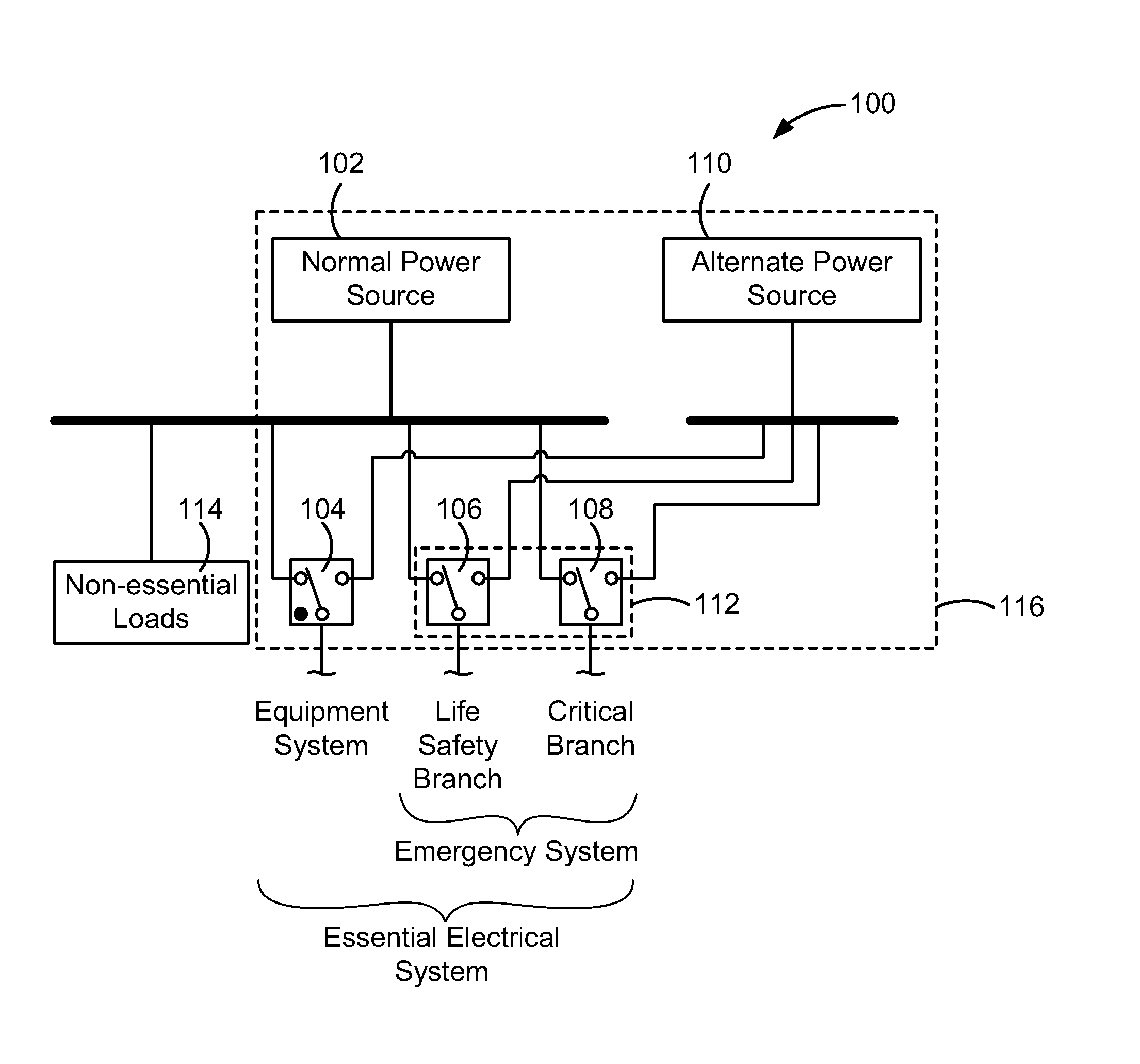
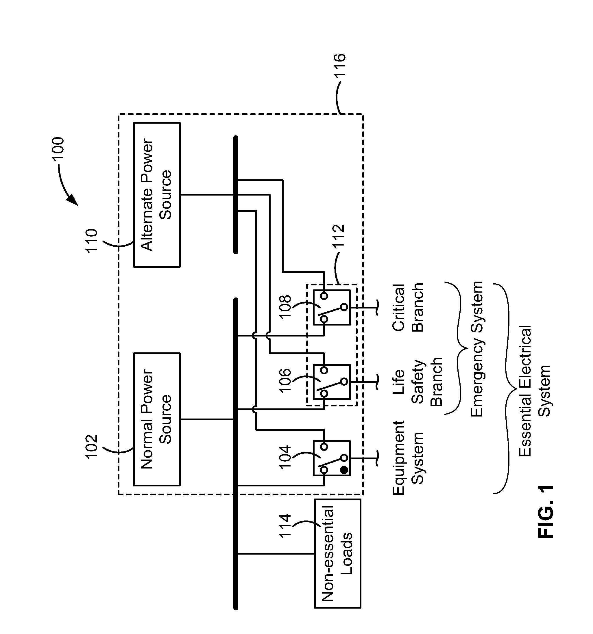
[0108]FIG. 1 is a functional block diagram of an example electrical system 100 that normally supplies electrical current to electrical loads within a facility or building, such as a hospital or healthcare facility, from a normal power source 102. When power supplied by the normal power source 102, such as a main utility power source, is interrupted, automatic switching equipment 104, 106, 108 automatically switches power supplied by the normal power source 102 to an alternate power source 110, such as a generator or genset, as that term is understood by those skilled in the art of power systems, or a direct current (DC) power source such as a battery. In the case of a hospital, the electrical system 100 can include an emergency system 112 that supplies power to essential loads within the hospital that are supplied by life safety or critical branch circuits. Non-essential loads 114 in the hospital remain unpowered during a power outage from the normal power source 102. Within the ess...


PUM


Abstract

An automated emergency power supply system (EPSS) and testing solution that records generator load values and engine exhaust temperature values to evaluate whether an EPSS test satisfies legislated test criteria. The EPSS test is carried out under software control, which initiates a test by instructing an automatic transfer switch (ATS) to change its status to a test status, causing the essential loads to be powered by a generator instead of a main utility power source. Power monitors record the ATS and generator status during the test as well as electrical parameter data from the ATS and generator and exhaust temperature data and other engine parameter data from the generator. When the test is concluded, the ATS is instructed to return the status to normal so that power delivery is resumed from the main power source. The electrical and engine parameter data is analyzed and compared against legislated test criteria to determine a pass/fail result of the EPSS test.

Description


Claims


Application Information

Patent Timeline
03 May 2012
Publication
US20120105097A1