Signal Controlling Method for 3D Image Display Device

a display device and signal control technology, applied in the field of three-dimensional stereoscopic images, can solve the problems of not meeting the environmental protection concept, affecting the image resolution, and affecting the image resolution, and achieve the effect of complete image resolution

Inactive Publication Date: 2012-05-03
CHUNGHWA PICTURE TUBES LTD
View PDF4 Cites 0 Cited by
  • Summary
  • Abstract
  • Description
  • Claims
  • Application Information

AI Technical Summary

Benefits of technology

[0010]One advantage of the present invention is that the 3D image signal controlling method can render the user to see 3D stereoscopic images no matter the user wears the circularly polarized glasses at any angles.
[0011]Another advantage of the present invention is that the left eye image with the left-circularly polarized light or the right eye image with the right-circularly polarized light generated by the present invention will have complete image resolution in the horizontal or vertical direction and will not suffer the problem of the insufficient vertical resolution.
[0012]Furthermore, another advantage of the present invention is that the circularly polarized glasses in cooperation with the 3D image display device do not require batteries and emitter, such that the issues of the limited effective distance between the 3D glasses and the emitter and shielding by other objects and the charging problems or the environment pollution problems will be eliminated.

Problems solved by technology

The active type 3D glasses are the relatively common 3D glasses in the market, but it suffers some problems.
For example, the active type 3D glasses need batteries and therefore it induces the charging problem and it does not satisfy the environmental protection concept.
Furthermore, the effective distance between the active type 3D glasses and the emitter is limited and the signal emitted from the emitter may be shielded by any objects between the active type 3D glasses and the emitter.
Moreover, the active type 3D glasses are expensive.
Therefore, when the user wears the 3D glasses in an unacceptable angle or observes an object through the 3D glasses in an unacceptable angle of view, it will cause that the image is blocked and influences the 3D observation.

Method used


Image

  • Signal Controlling Method for 3D Image Display Device
  • Signal Controlling Method for 3D Image Display Device
  • Signal Controlling Method for 3D Image Display Device

Examples


Embodiment Construction

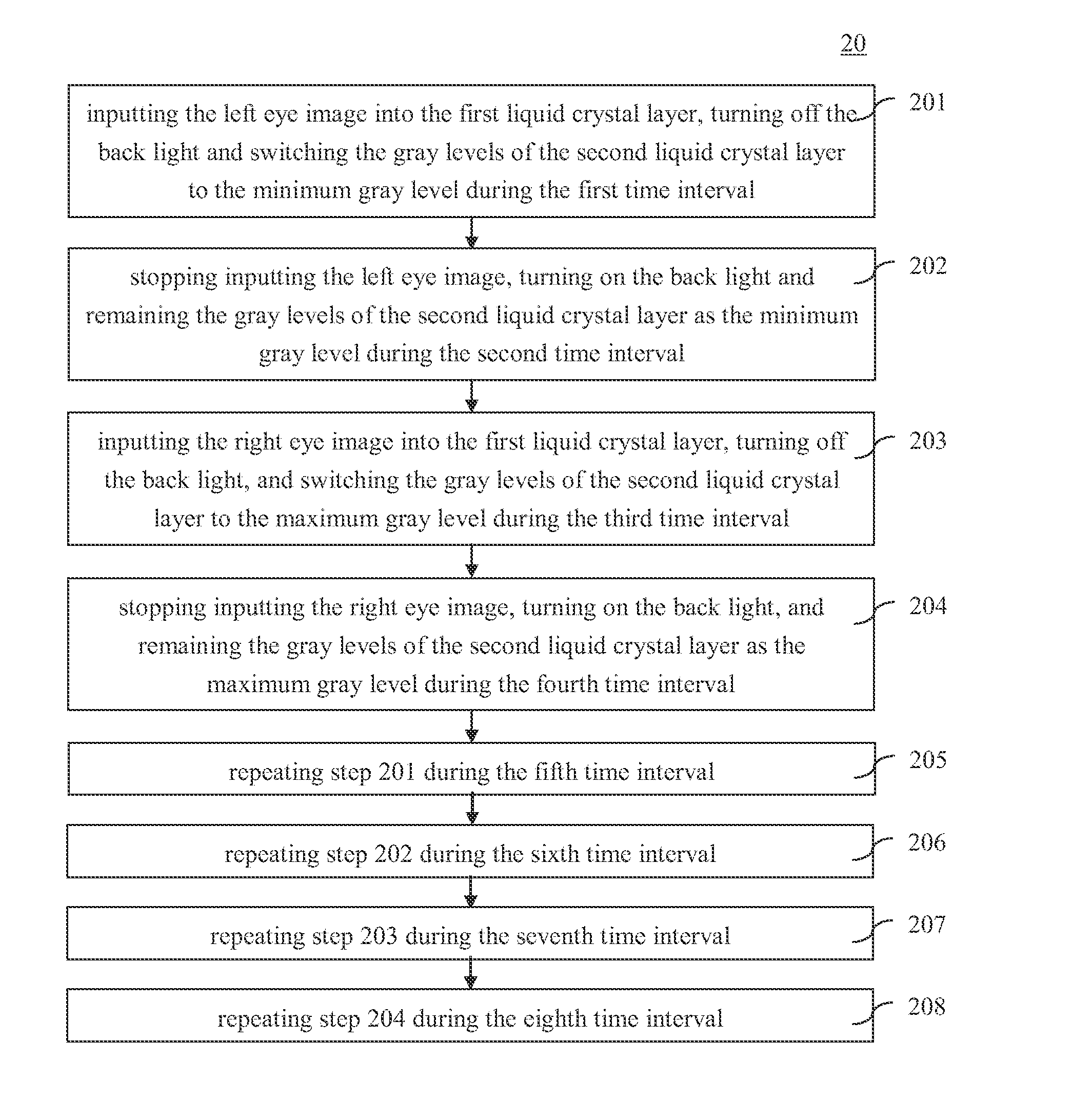
[0022]The invention will now be described with the preferred embodiments and aspects and these descriptions interpret structure and procedures of the invention only for illustrating but not for limiting the Claims of the invention. Therefore, except the preferred embodiments in the specification, the present invention may also be widely used in other embodiments.

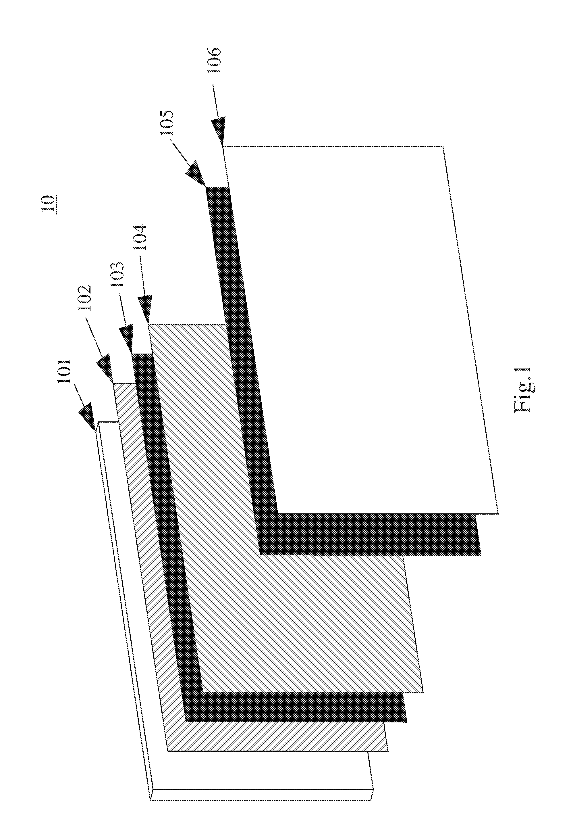
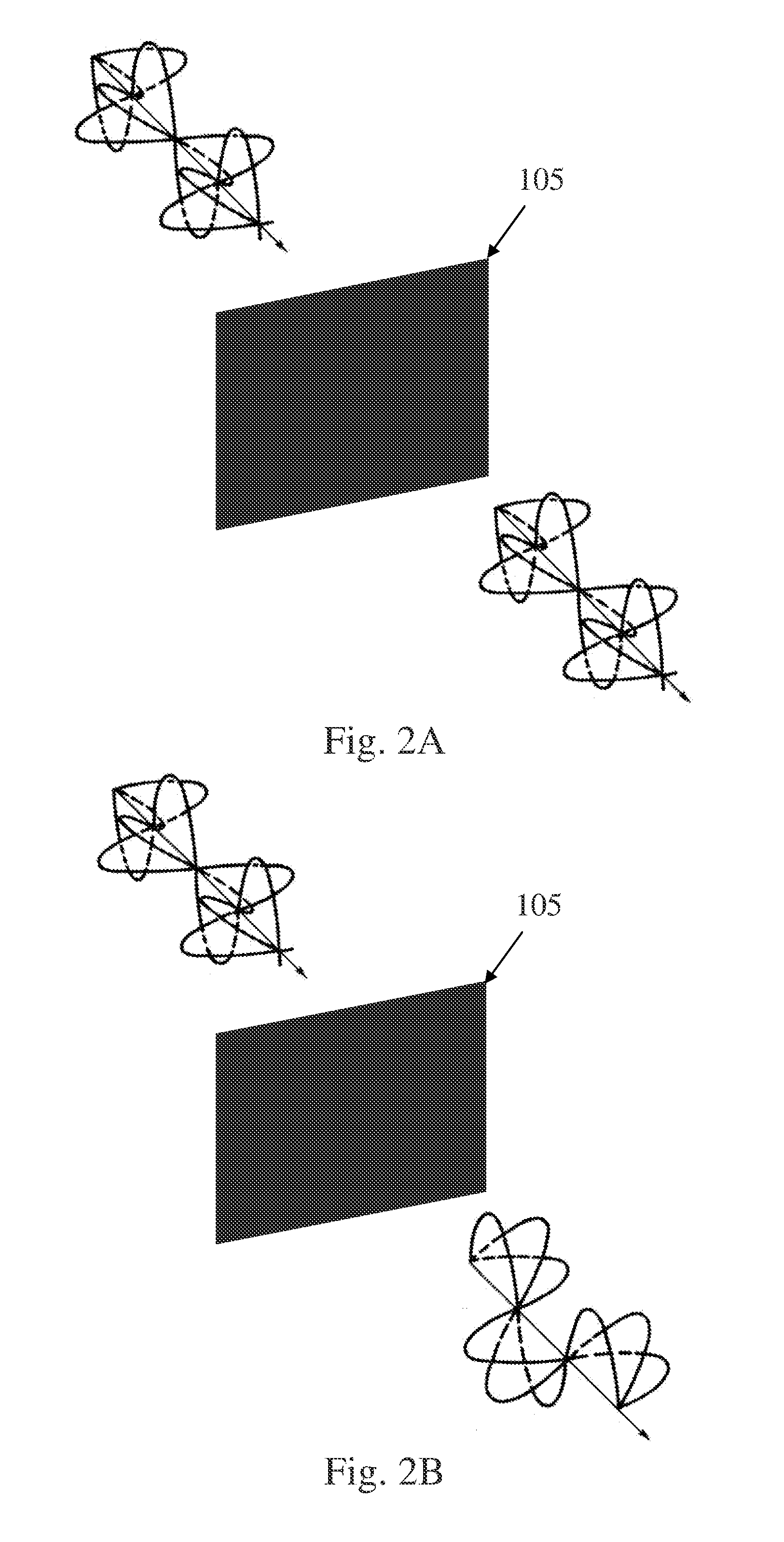
[0023]The present invention provides a 3D image display device. As shown in FIG. 1, the 3D image display device 10 of the present invention includes a backlight module 101 to provide the back light, and a first linear polaroid 102 disposed in front of the backlight module 101 to polarize the light from the backlight module 101. A first liquid crystal layer 103 is disposed in front of the first linear polaroid 102 to display image signals. A second linear polaroid 104, a second liquid crystal layer 105 and a retarding layer 106 are disposed in order in front of the first liquid crystal layer 103, successively. In other words,...


PUM


Abstract

The present invention provides a 3D image signal controlling method. The method comprises inputting a left eye image into the first liquid crystal layer, turning off the backlight module and switching gray levels of the second liquid crystal layer to a minimum gray level during (4N−3)th time interval, wherein N is natural number; stopping inputting the left eye image, turning on the backlight module and remaining the gray levels of the second liquid crystal layer as the minimum gray level during (4N−2)th time interval; inputting a right eye image into the first liquid crystal layer, turning off the backlight module and switching the gray levels of the second liquid crystal layer as a maximum gray level during (4N−1)th time interval; and stopping inputting the right eye image, turning on the backlight module and remaining the gray levels of the second liquid crystal layer as the maximum gray level during (4N)th time interval.

Description

CROSS-REFERENCE[0001]The present application is a continuation application of a U.S. patent application Ser. No. 12 / 938,389, entitled “3D Image Display Device”, and filed on Nov. 3, 2010, which is incorporated herein by reference in its entirety.TECHNICAL FIELD[0002]The present invention relates to three dimensional stereoscopic images, and more particularly to a signal controlling method for a 3D image display device.BACKGROUND OF THE RELATED ART[0003]Three dimensional stereoscopic image display technology has become the current trend in the image display technology field. The imaging theorem for the three dimensional stereoscopic image involves that seeing a target object by a left eye and a right eye to get the different images, thereby forming depth perceptions with farness and nearness. Multiple devices can be utilized to render the left eye and the right eye to see images with different views. Three dimensional image display devices can be classified as a glasses type and a ba...

Claims


Application Information

Patent Timeline
Patent Type & Authority Applications(United States)
IPC IPC(8): G09G3/36G09G5/10G02B30/25
CPCH04N13/337G02B27/26G02B30/25
Inventor LIN, SHIH-CHIEHLIN, HSIANG-TANCHEN, CHIEN-HUNGCHIU, CHUN-CHIEH
Owner CHUNGHWA PICTURE TUBES LTD
Why Eureka
Try Eureka