
Biomimetic compound eye optical sensor and fabricating method thereof

a compound eye and optical sensor technology, applied in the direction of direction/deviation determining electromagnetic systems, instruments, other domestic articles, etc., can solve the problems of limitation in miniaturizing existing optical systems and increasing demand for micro imaging systems

Active Publication Date: 2012-05-03
SAMSUNG ELECTRONICS CO LTD +1
View PDF1 Cites 3 Cited by
  • Summary
  • Abstract
  • Description
  • Claims
  • Application Information

AI Technical Summary

Benefits of technology

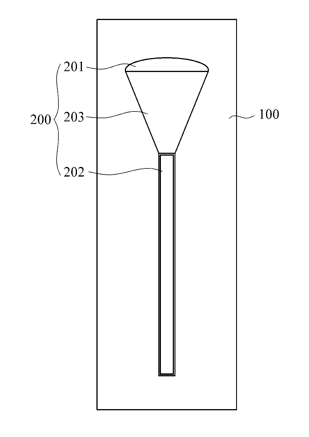
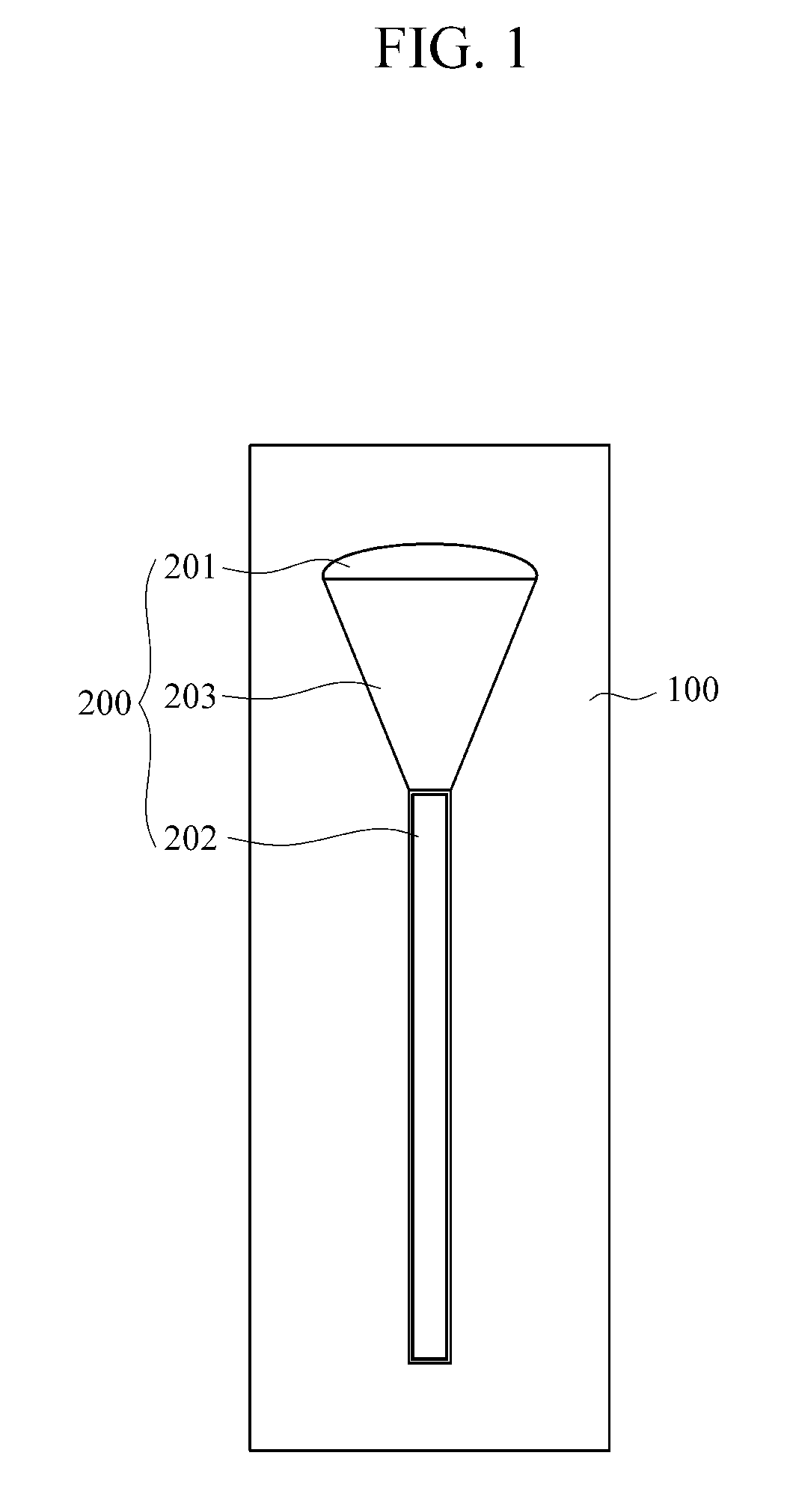
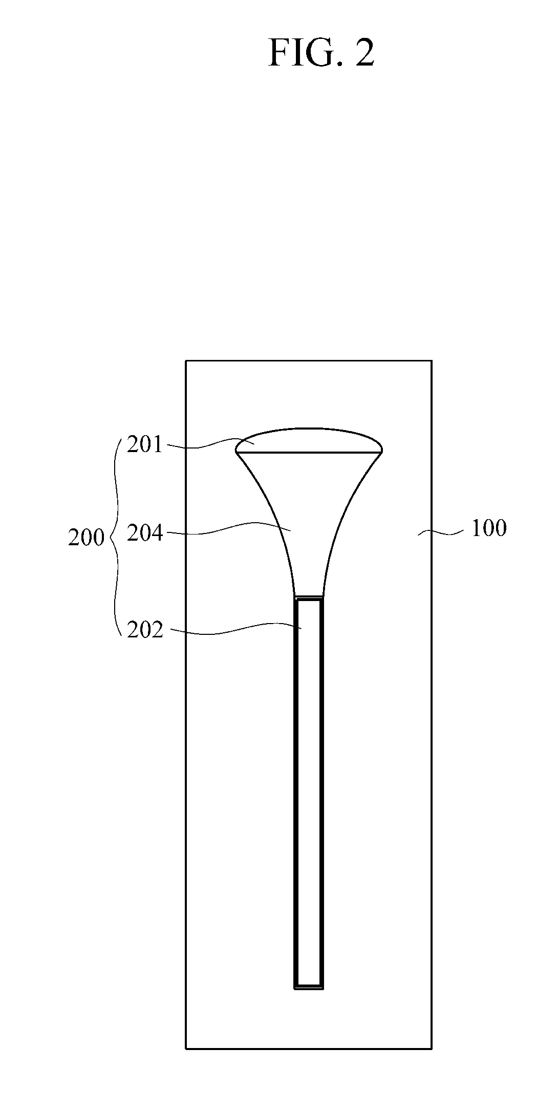
[0009]According to an aspect of an exemplary embodiment, there is provided an optical sensor including: a substrate; and an ommatidia located on or inside the substrate, the ommatidia including a microlens which receives light, an optical waveguide which transfers the light received through the microlens, and a cone structure including a first end connected to the microlens and a second end connected to the optical waveguide, the cone structure having a diameter or a width decreasing in a direction from the first end to the second end.
[0010]Accordin...

Problems solved by technology

In particular, recently, demands for micro imaging systems are increasing, though there is a limitation in miniaturizing existing optical systems.

Method used


Image

  • Biomimetic compound eye optical sensor and fabricating method thereof
  • Biomimetic compound eye optical sensor and fabricating method thereof
  • Biomimetic compound eye optical sensor and fabricating method thereof

Examples


Embodiment Construction

[0020]The following description is provided to assist the reader in gaining a comprehensive understanding of the methods, apparatuses, and / or systems described herein. Accordingly, various changes, modifications, and equivalents of the methods, apparatuses, and / or systems described herein will be suggested to those of ordinary skill in the art. Also, descriptions of well-known functions and constructions may be omitted for increased clarity and conciseness.

[0021]FIG. 1 illustrates an artificial ommatidia according to an exemplary embodiment.

[0022]Referring to FIG. 1, the artificial ommatidia includes a substrate unit 100 and an ommatidia unit 200.

[0023]The substrate unit 100 includes a material having a first refractive index with respect to light. For example, the substrate unit 100 may be a glass plate.

[0024]The ommatidia unit 200 is on or inside the substrate unit 100. The ommatidia unit 200 may include a material having a second refractive index that is different from the first ...


PUM


Abstract

Provided is an optical sensor and an optical sensor fabricating method. The optical sensor includes: a substrate; and an ommatidia located on or inside the substrate, the ommatidia comprising a microlens which receives light, an optical waveguide which transfers the light received through the microlens, and a cone structure comprising a first end connected to the microlens and a second end connected to the optical waveguide, the cone structure having a diameter or a width decreasing in a direction from the first end to the second end.

Description

CROSS-REFERENCE TO RELATED APPLICATION[0001]This application claims priority from Korean Patent Application No. 10-2010-0107109, filed on Oct. 29, 2010 in the Korean Intellectual Property Office, the entire disclosure of which is incorporated herein by referenceBACKGROUND[0002]1. Field[0003]Apparatuses and methods consistent with exemplary embodiments relate to a biomimetic compound eye optical sensor, and a fabricating method thereof.[0004]2. Description of the Related Art[0005]Insects are among organisms that exist in the natural world that have compound eyes. A compound eye includes many ommatidiums. In other words, each ommatidium is a unit configuring a compound eye. As such, since the insect's eye is a compound eye including many ommatidiums, the insect has a wider viewing angle than other mammals.[0006]In general, biomimetics is a technology of developing an abiotic system by imitating the systems of organisms. Recently, studies into a technology of developing optical systems...

Claims


Application Information

Patent Timeline
IPC IPC(8): G02B6/00G02B6/42
CPCG02B6/06G01S3/783G02B6/32G02B6/4206G02B6/4221H01L27/14625H04N23/687
Inventor JUNG, KYU-DONGJEONG, KI-HUNKEUM, DONG-MIN
Owner SAMSUNG ELECTRONICS CO LTD
Learn More