
Air pump having an impeller with double-sided blades

Inactive Publication Date: 2012-05-03
DONGGUAN TIGER POINT METAL & PLASTIC PRODS
View PDF2 Cites 10 Cited by
  • Summary
  • Abstract
  • Description
  • Claims
  • Application Information

AI Technical Summary

Benefits of technology

[0005]An objective of the present invention is to provide an air pump having an impeller with double-sided blades that is mounted outside an inflatable product to be inflated or deflated, and has double-sided blades on the impeller for enhancing the inflation efficiency and deflation efficiency of the air pump.
[0011]Due to the impeller having the double-sided blades and the air guide channels, air can be efficiently inflated to an inflatable product through two paths respectively going through the first air inlet, the first air chamber and the second air inlet to the inflatable product and going through the first supplement air inlets, the second air chamber, the second supplement air inlet, the first air chamber and the second air inlet to the inflatable product, or deflated air from the inflatable product respectively through the first air inlet to the second air inlet, and through the deflation passage, the air guide channels of the impeller opposite to the first air inlet to the second air inlet. As the air flow increases in inflation and deflation, the inflation and deflation efficiency of the air pump is enhanced accordingly.

Problems solved by technology

Despite having the functions of inflation, deflation and maintaining pressure, the inflatable products with air pumps are practically unsatisfactory in performing the aforementioned functions and lag far behind in achieving the expected operation effect.
The consequence is that the number of parts constantly increases to result in a lower yield in production and rising material cost, mold cost and production cost and in turn less competitive edge in the market.
Another drawback is that conventional air pumps adopt an impeller having single-sided blades which is a less efficient design setting a barrier limiting the performance of inflation and deflation.

Method used


Image

  • Air pump having an impeller with double-sided blades
  • Air pump having an impeller with double-sided blades
  • Air pump having an impeller with double-sided blades

Examples


Embodiment Construction

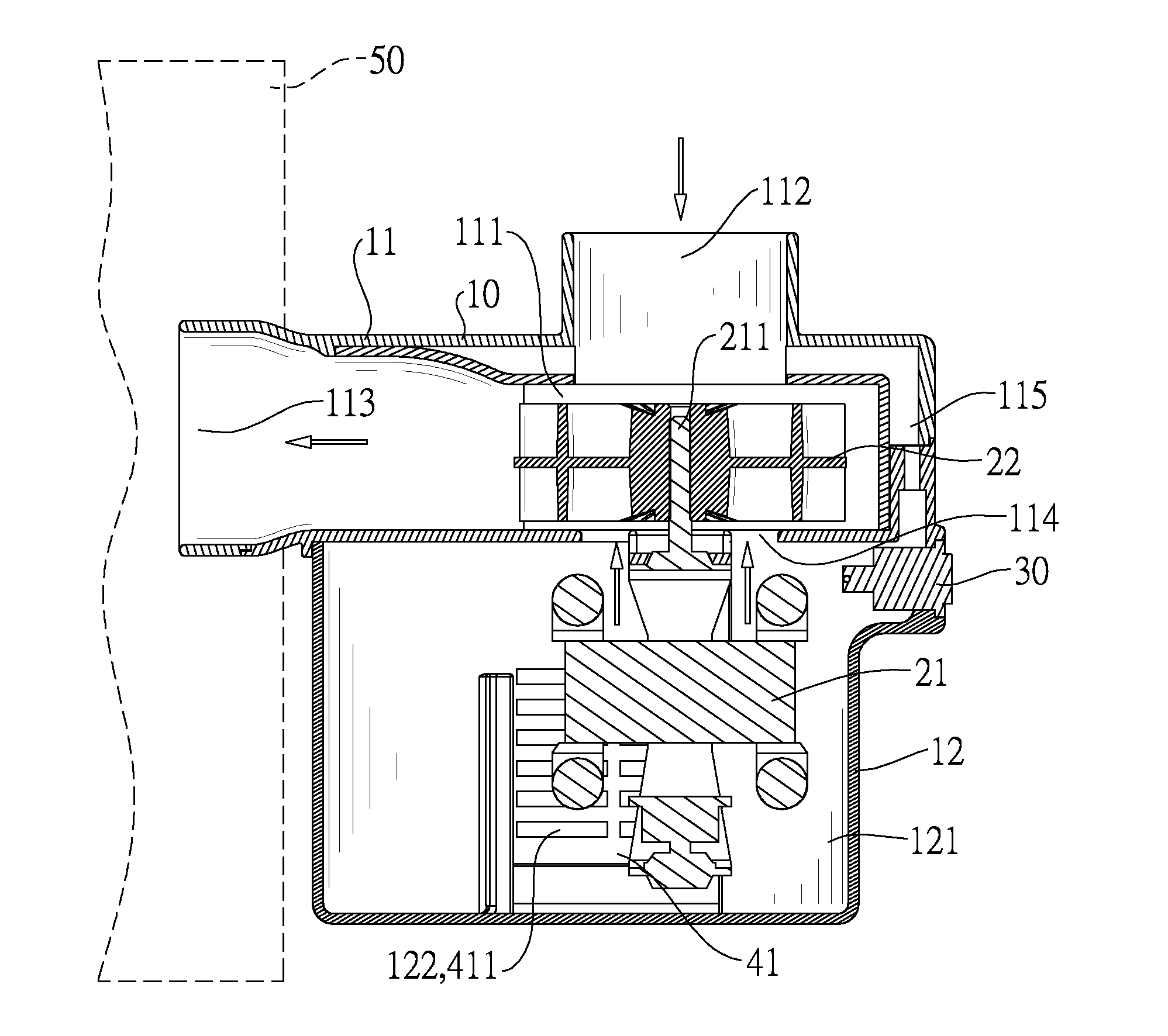
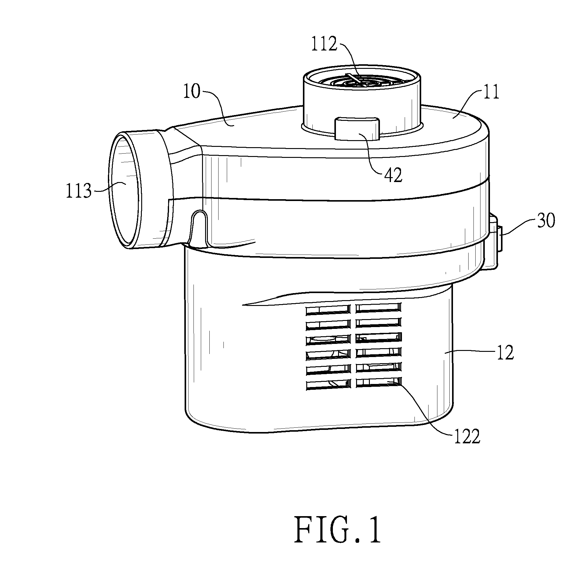
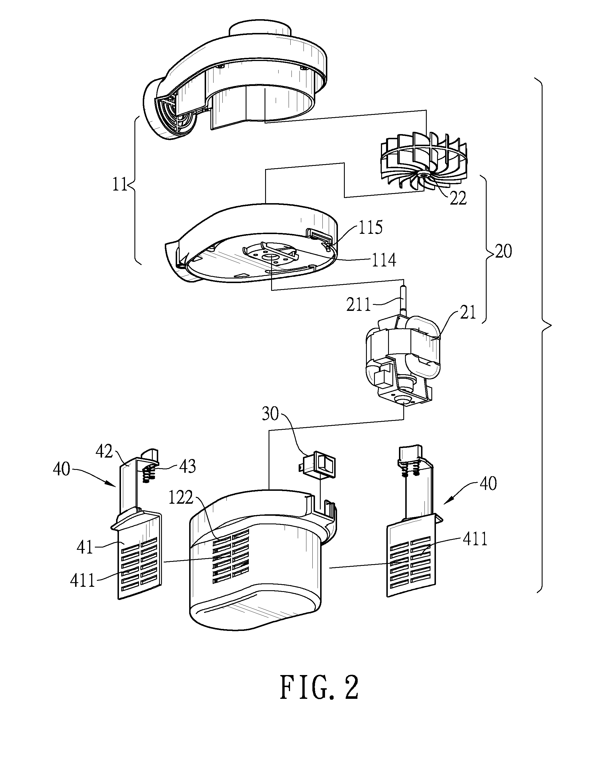
[0021]With reference to FIGS. 1 to 8, an air pump having an impeller with double-sided blades has a body 10, a blower 20, a power switch 30 and two air valves 40.

[0022]The body 10 has a top casing 11 and a bottom casing 12. The top casing 11 has a first air chamber 111, a first air inlet 112, a second air inlet 113 and a deflation passage 115. The first air chamber 111 is formed inside the top casing 11. The first air inlet 112 is formed at one end of the first air chamber 111, and the second air inlet 113 is formed at another end of the first air chamber 111. The first and second air inlets 112, 113 are circular openings and protrude from the body 10. The deflation passage 115 is formed inside the top casing 11 and communicates with the first air inlet 112. The bottom casing 12 is combined on a bottom of the top casing 11, and has a second air chamber 121, multiple first supplement air inlets 122, and a second supplement air inlet 114. The second air chamber 121 is defined between ...


PUM


Abstract

An air pump having an impeller with double-sided blades is mounted outside an inflatable product, and has a body and a blower. The body has a first air chamber and a second air chamber communicating with each other, a first air inlet and a second air inlet formed at two ends of the first air chamber, and multiple first supplement air inlets formed through the body to communicate with the second air chamber. The blower has a motor and an impeller. The impeller driven by the motor has multiple double-sided blades capable of efficiently inflating air from the multiple first supplement air inlets or deflating air from the first air inlet. The air pump achieves to be more efficient in inflating and deflating the inflatable product, and structurally simplified to facilitate production and assembly of the air pump and cost reduction in production and assembly.

Description

BACKGROUND OF THE INVENTION[0001]1. Field of the Invention[0002]The present invention relates to an air pump, and more particularly to an air pump mounted outside an inflatable product to be inflated or deflated, and having an impeller with double-sided blades formed on the impeller for enhancing the inflation efficiency and deflation efficiency of the air pump.[0003]2. Description of the Related Art[0004]Air pumps are critical parts for inflatable products such as inflatable mattress, inflatable jumping bed, inflatable sofa, inflatable toy, above ground pool and the like, and are usually mounted inside inflatable bodies of the inflatable products for the purpose of rapidly inflating and deflating and maintaining pressure of the inflatable products. Accordingly, the inflatable products can be in use or stored after being inflated or deflated. Despite having the functions of inflation, deflation and maintaining pressure, the inflatable products with air pumps are practically unsatisf...

Claims


Application Information

Patent Timeline
IPC IPC(8): F04B35/04
CPCF04D29/282F04D17/162F04D25/084F04D29/424
Inventor TSAI, CHUN-CHUNG
Owner DONGGUAN TIGER POINT METAL & PLASTIC PRODS
Learn More