Spindle and adapter for roll paper product dispensers

a technology of product dispensers and adapters, which is applied in the field of dispensers, can solve the problems of increasing the time required for reloading the spindle, unable to provide a simple design for the spindle with rotating ends, and requiring at least four separate parts, so as to facilitate the first section and facilitate the inserting of the first section. , the effect of easy insertion into the center apertur

Active Publication Date: 2012-05-10
SOLARIS PAPER
View PDF22 Cites 30 Cited by
  • Summary
  • Abstract
  • Description
  • Claims
  • Application Information

AI Technical Summary

Benefits of technology

[0010]In one aspect of some preferred embodiments, the spindle's elongated member has a hollow interior and side openings. Each side opening preferably has a diameter smaller than the inner diameter of the hollow interior. In addition, the end members each have first, second, and third sections. The first section has a maximum diameter smaller than the diameter of the hollow interior and larger than the diameter of the first and second openings. The second section has a maximum diameter smaller than the diameter of the side openings. The third section has a maximum diameter greater than the diameter of the hollow interior. The first section of each end member can be inserted into the side openings of the elongated member and snapped into place in a manner that allows the elongated member to rotate with respect to the end members. The elongated member is preferably made of a material that has sufficient elasticity to allow its side openings to expand (e.g., bend out...

Problems solved by technology

Unfortunately, the spindle in Moody is complex and requires at least four separate parts.
Furthermore, assembling the spindle requires many steps, which increases the time required to re-load the spindle with a new roll of paper product.
Moody and all other known prior art have failed to provide a simple design for a spindle having rotating ends.
Since coreless rolls generally have a smaller center aperture diameter than core rolls, the trigger mechanism in the dispenser is activated prematurely when coreless rolls a...

Method used


Image

  • Spindle and adapter for roll paper product dispensers
  • Spindle and adapter for roll paper product dispensers
  • Spindle and adapter for roll paper product dispensers

Examples


Embodiment Construction

[0025]The following discussion provides many example embodiments of the inventive subject matter. Although each embodiment represents a single combination of inventive elements, the inventive subject matter is considered to include all possible combinations of the disclosed elements. Thus if one embodiment comprises elements A, B, and C, and a second embodiment comprises elements B and D, then the inventive subject matter is also considered to include other remaining combinations of A, B, C, or D, even if not explicitly disclosed.

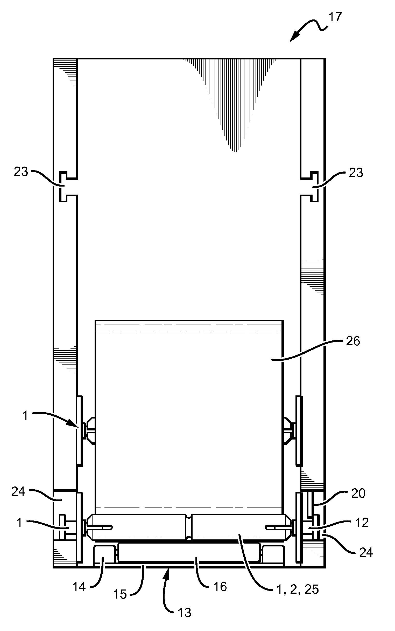
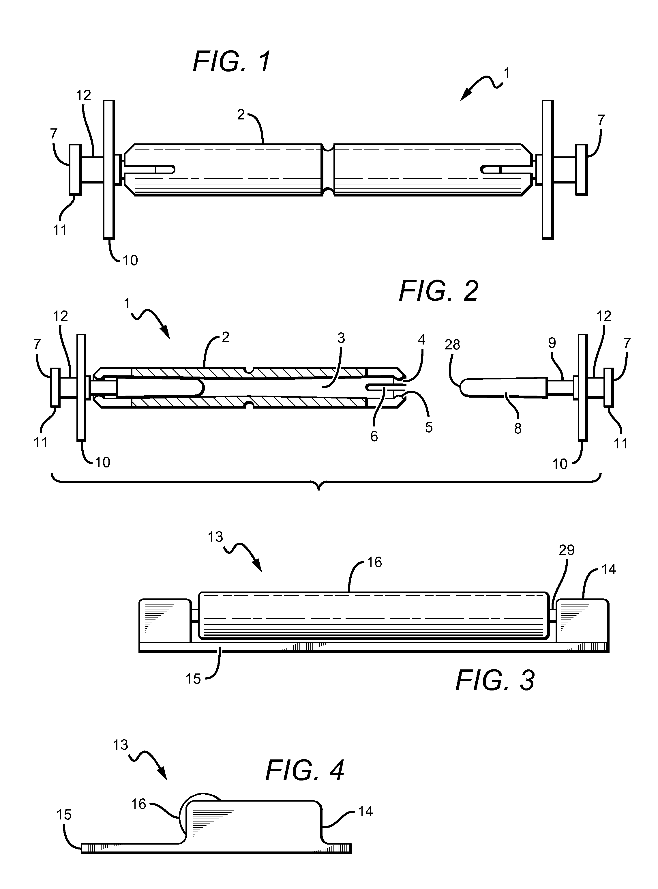
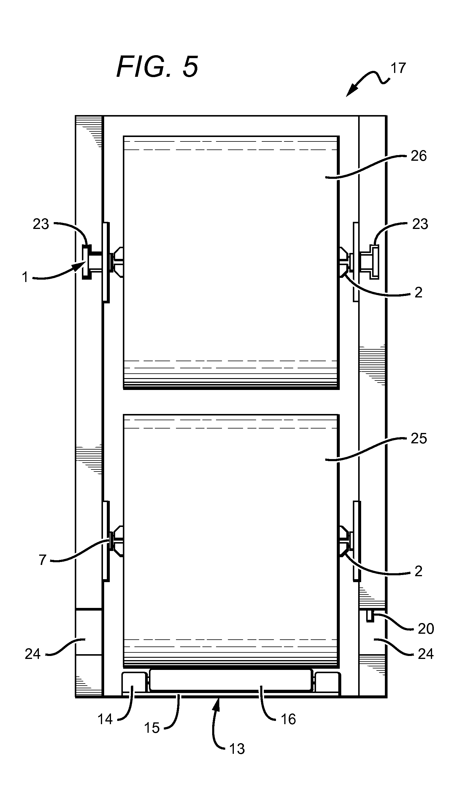
[0026]FIG. 1 shows a front view of a spindle 1, which incorporates an elongated member 2 and two identical end members 7. End members 7 are configured to rotatably and removable couple with elongated member 2. Loading a roll of toilet paper requires the removal of one of the end members 7 from elongated member 2. Once the roll of toilet paper is loaded onto elongated member 2, the removed end member 7 can be snapped back into the hollow interior 3 (see FIG....


PUM


Abstract

A spindle for dispensing a roll of paper product is described. The spindle has an elongated member rotatably coupled with two side members. The side members have different sections of various diameters, which are configured to allow a portion of the side members to be inserted into a hollow interior of the elongated member. The elongated member has sufficient elasticity to provide a snap connection with the side members. The side members are configured to engage a track in a dispenser. Furthermore, at least one of the side members is removable. Also described herein is a roller assembly for adapting a dispenser. The assembly comprises a spindle rotatably coupled with a housing. The housing includes a fastener for attaching the housing to a dispenser. The roller assembly is configured to raise a roll of paper product, thus allowing dispensers originally designed for core rolls to be used with coreless rolls.

Description

[0001]This application claims the benefit of priority to U.S. provisional patent application Ser. No. 61 / 409,626, filed on Nov. 3, 2010.FIELD OF THE INVENTION[0002]The field of the invention is dispensers, more specifically, spindles with rotatable ends for dispensing roll paper products.BACKGROUND[0003]Spindles are commonly used for winding and unwinding roll paper products (e.g., toilet paper, paper towels). Numerous designs for spindles and dispensers have been developed over the years. See, for example, U.S. Pat. Nos. 1,391,326, 1,778,856, 2,209,471, 2,289,453, 2,289,519, 2,331,743, 2,621,867, 2,762,575, 3,770,221, 4,212,434, 4,422,585, 4,447,015, 5,370,336, 5,669,576, 5,669,576, 6,422,505, D0,340,822, International Patent Application Publication No. WO 2009 / 027873, and Great Britain Patent No. 731449.[0004]These and all other extrinsic materials discussed herein are incorporated by reference in their entirety. Where a definition or use of a term in an incorporated reference is ...

Claims


Application Information

Patent Timeline
IPC IPC(8): A47K10/22B65H23/04B65H75/02A47K10/38
CPCB65H75/185A47K10/40B65H75/2254B65H75/2245
Inventor PHELPS, STEPHEN LAWRENCE
Owner SOLARIS PAPER
Why Eureka
Try Eureka