Charger circuit

a charging circuit and charger technology, applied in the direction of transportation and packaging, sustainable buildings, greenhouse gas reduction, etc., can solve the problems of limited conventional charging circuit, long charging time, battery cannot be charged,

Active Publication Date: 2012-05-10
RICHTEK TECH
View PDF10 Cites 23 Cited by
  • Summary
  • Abstract
  • Description
  • Claims
  • Application Information

AI Technical Summary

Problems solved by technology

Such conventional charger circuit is limited by the over temperature protection mechanism of the circuit; that is, the battery cannot be charged with a large current.
Therefore, the charging time is long, and the charging efficiency is poor.
Furthermore, due to heat dissipation issue of the charging path 11, the efficiency of the charging circuit 10 is further degraded.

Method used


Image

  • Charger circuit
  • Charger circuit
  • Charger circuit

Examples


Embodiment Construction

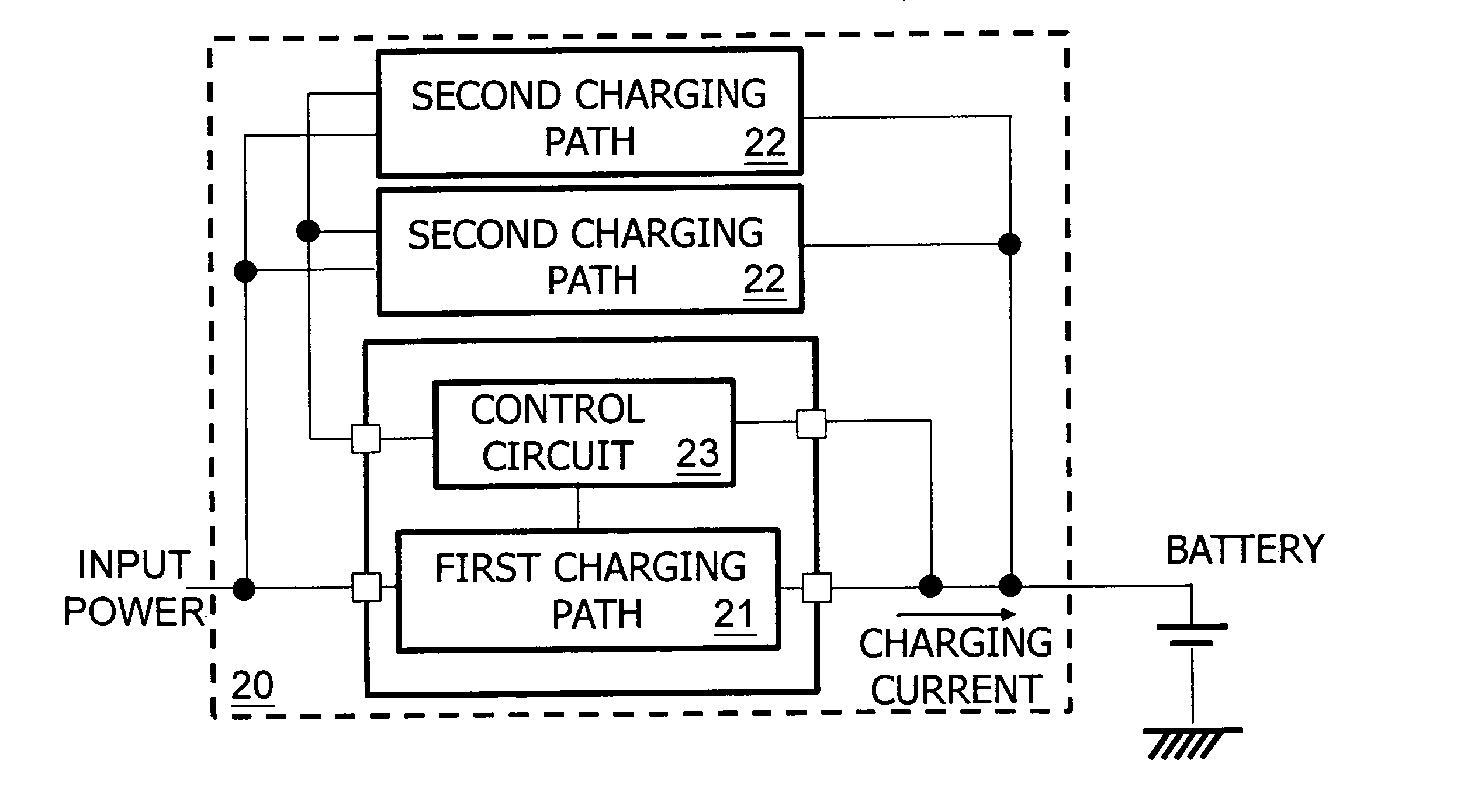
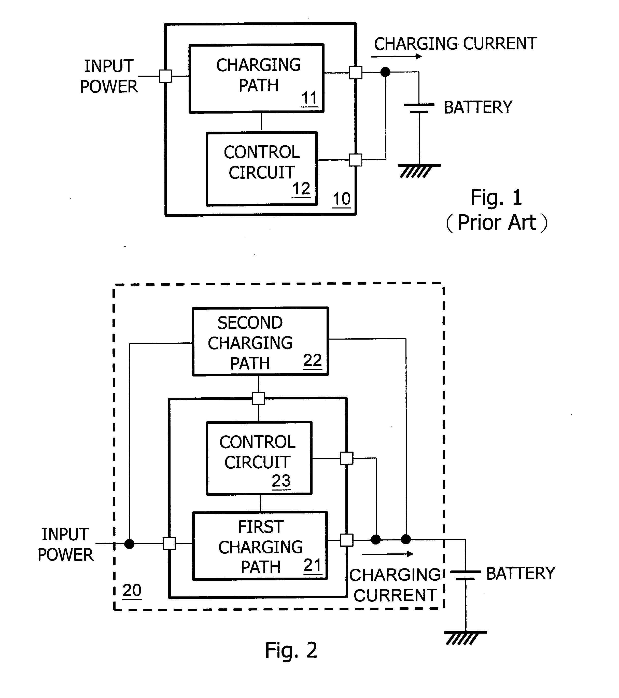
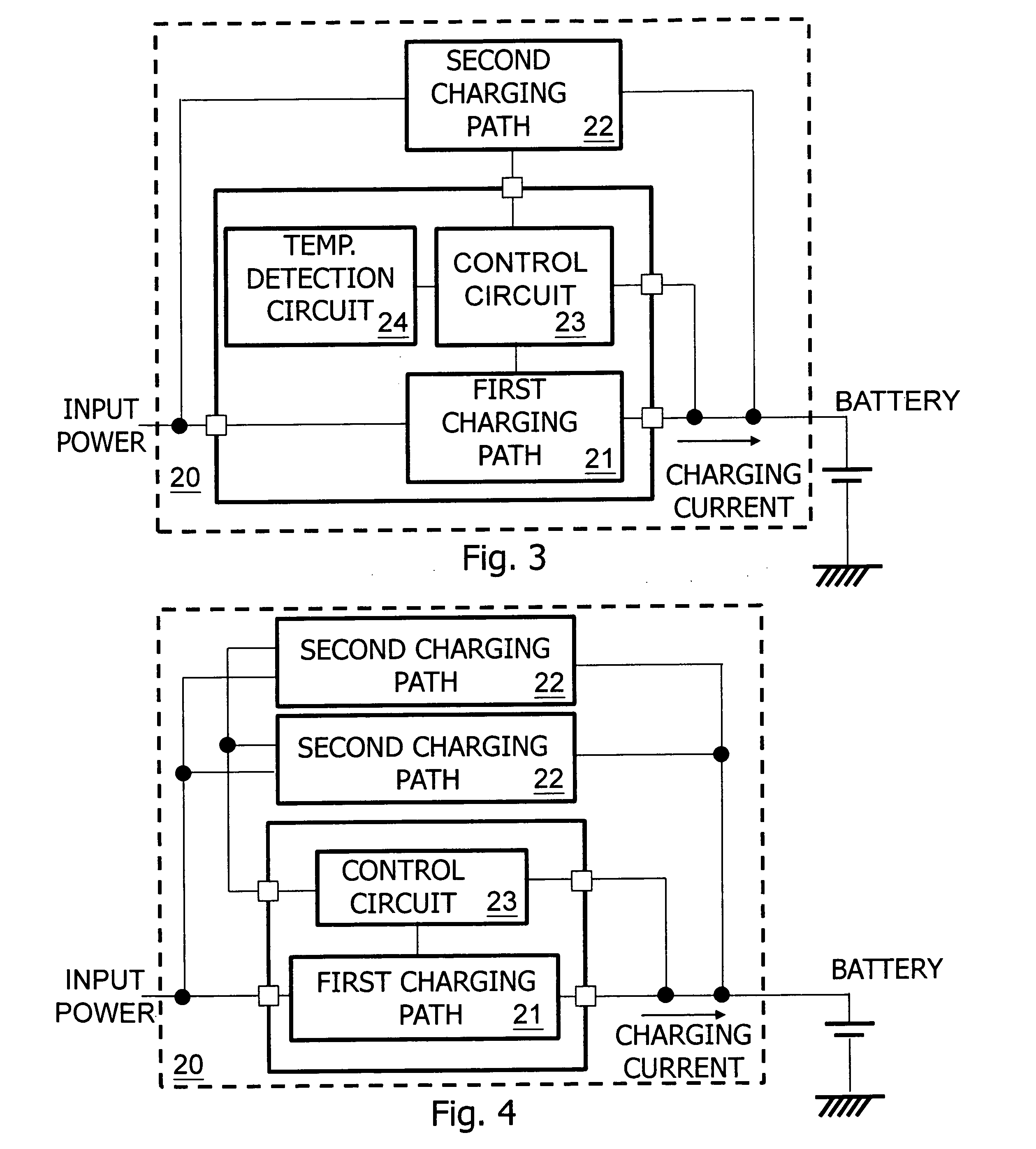
[0018]Referring to FIG. 2, it shows an embodiment of the present invention. The object to be charged is not limited to the DC battery as shown for example, but may be various other electrical energy storage devices. As shown in this figure, input power supplies a battery with a charging current for charging the battery through the first charging path 21 and the second charging path 22 of a charger circuit 20. A control circuit 23 obtains a battery feedback signal (which may be, for example but not limited to, the voltage or the divided voltage of the battery) related to a battery charging status from the battery, and controls the first charging path 21 and the second charging path 22 accordingly. In one embodiment, the charging paths are controlled as thus. When the battery voltage is below a first predetermined threshold, the control circuit 23 generates a first control signal and a second control signal, activating both the first charging path 21 and the second charging path 22 to...


PUM


Abstract

The present invention discloses a charger circuit. The charger circuit comprises a control circuit and at least two charging paths. The control circuit determines to activate or inactivate each charging path according to a battery feedback signal representing the charging status. Accordingly, the battery is charged by input power in an optimal way so that the charging efficiency is improved and the overheating problem is solved.

Description

CROSS REFERENCE[0001]The present invention claims priority to TW 099221755, filed on Nov. 10, 2010.BACKGROUND OF THE INVENTION[0002]1. Field of Invention[0003]The present invention relates to a charger circuit, in particular to such charger circuit which includes at least two charging paths.[0004]1. Description of Related Art[0005]FIG. 1 shows a schematic diagram of a prior art charger circuit. As shown in FIG. 1, input power supplies a battery with a charging current, charging the battery through the charging path 11 of a charger circuit 10. A control circuit 12 obtains a battery feedback signal related to a battery charging status from the battery, and controls the charging path 11 accordingly such that when the battery charging status reaches a predetermined threshold, the charging path 11 is inactivated to finish the charging operation.[0006]This conventional charger circuit charges the battery only by one charging path 11. In many applications, the charging path 11, the control...

Claims


Application Information

Patent Timeline
Patent Type & Authority Applications(United States)
IPC IPC(8): H02J7/04
CPCH02J7/0052Y02B40/90Y02E70/40H02J7/00Y02B40/00Y02E60/10Y02E60/13
Inventor WANG, HSUAN-KAIKUNG, NIEN-HUILI, WEI-I
Owner RICHTEK TECH
Why Eureka
Try Eureka