Device for Establishing an Anatomical Reference Point of an Intervertebral Disc

a technology of anatomical reference point and intervertebral disc, which is applied in the field of devices for establishing an anatomical reference point of an intervertebral disc, can solve the problems of affecting the implantation of the implant is precise and aligned, and the anterior and lateral approaches are relatively invasiv

Active Publication Date: 2012-05-10
NORGINE VENTURES BV
View PDF7 Cites 9 Cited by
  • Summary
  • Abstract
  • Description
  • Claims
  • Application Information

AI Technical Summary

Benefits of technology

[0005]The posterior approach involves fewer risks of complications and is further less invasive. The drawback of such an approach however lies in that the vision of the operative field is extremely reduced. Then, in order to enable the surgeon to visually accede the operative field, it is often necessary to remove bone materials.
[0008]So, thanks to the motions of the platform with respect to the means for bone anchorage and of the viewing element relative to the platform, an anatomical reference point of the intervertebral disc to be treated is obtained. The platform constitutes a reference point relative to the patient's spine and more particularly relating to the spinous processes crest of the at least two vertebras surrounding the disc to be replaced. The viewing element constitutes a reference point indicating the direction of the intervertebral disc to the replaced. The degrees of freedom of the adjusting elements with respect to each other make it possible to adjust the viewing element with respect to the intervertebral disc and thus to ensure a precise and aligned implantation of the implant in the intervertebral space obtained after the removal of the disc.

Problems solved by technology

The anterior and lateral approaches, however, have the drawback of being relatively invasive.
They also imply a surgical gesture which is delicate as regards the associated risks and difficult as regards technique.
The stage L5-S1 is particularly delicate because it requires pushing the aortas aside and so a bad estimation by the surgeon and an error in the gesture could involve vascular complications.
Other complications may further occur, such as post-operative pains which may require removing the positioned prosthesis and / or total osteosynthesis from the instrumented level.
The drawback of such an approach however lies in that the vision of the operative field is extremely reduced.

Method used


Image

  • Device for Establishing an Anatomical Reference Point of an Intervertebral Disc
  • Device for Establishing an Anatomical Reference Point of an Intervertebral Disc
  • Device for Establishing an Anatomical Reference Point of an Intervertebral Disc

Examples


Embodiment Construction

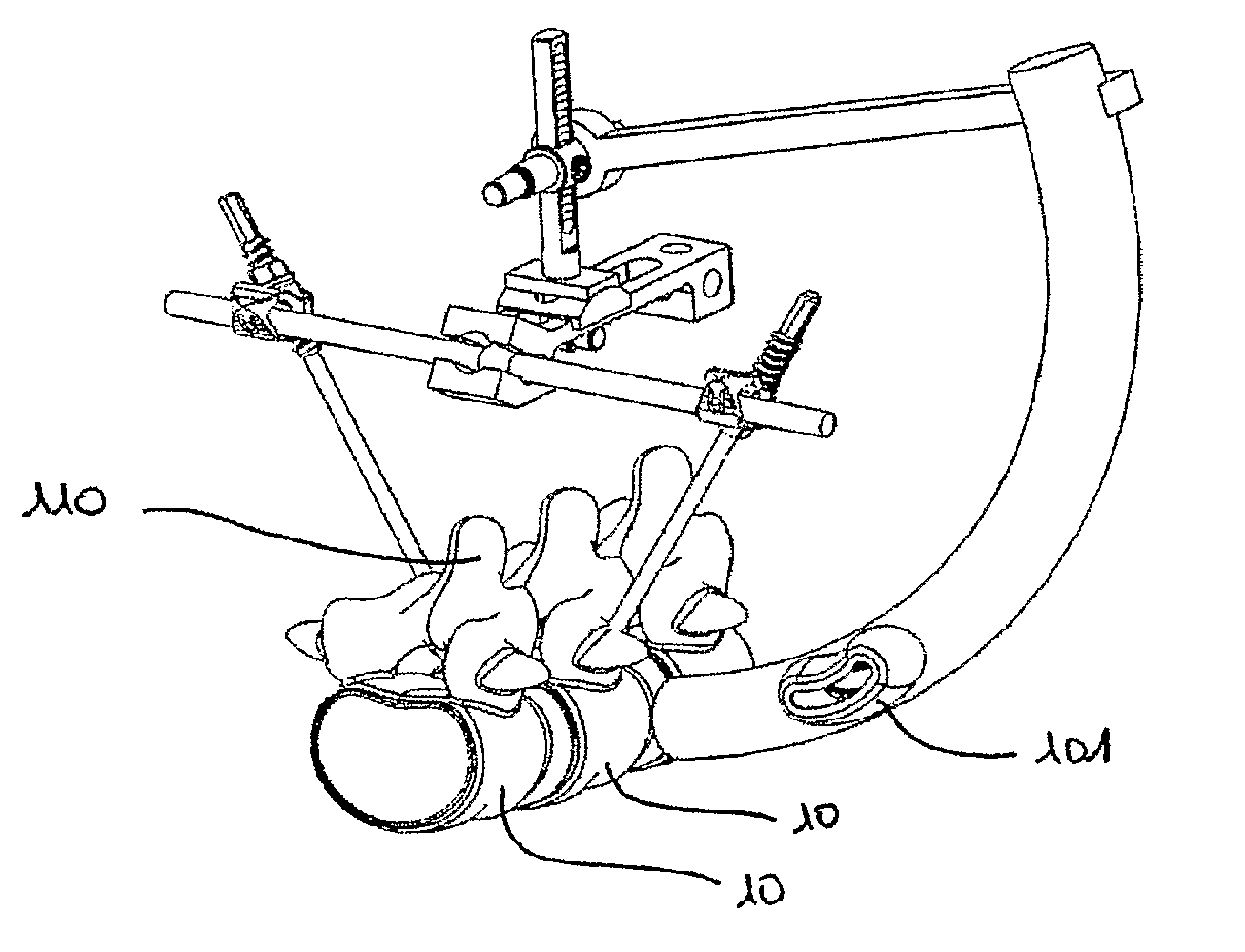
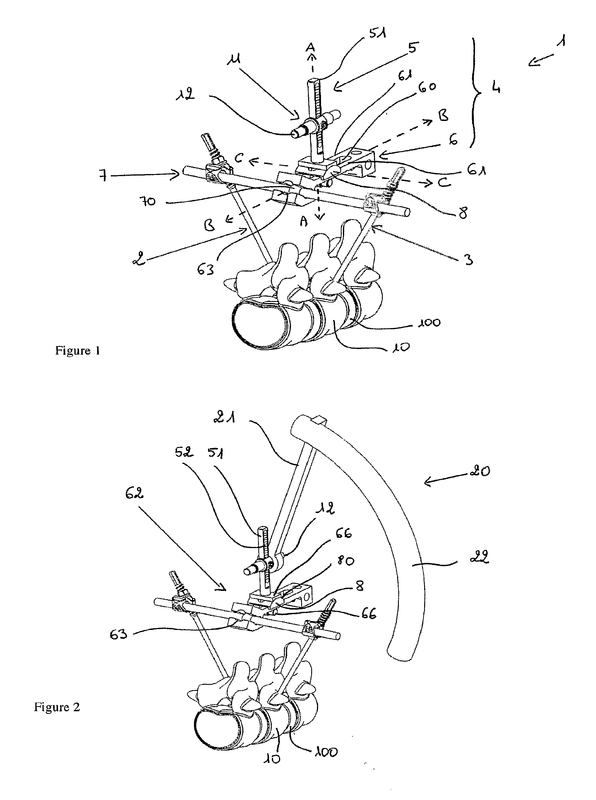
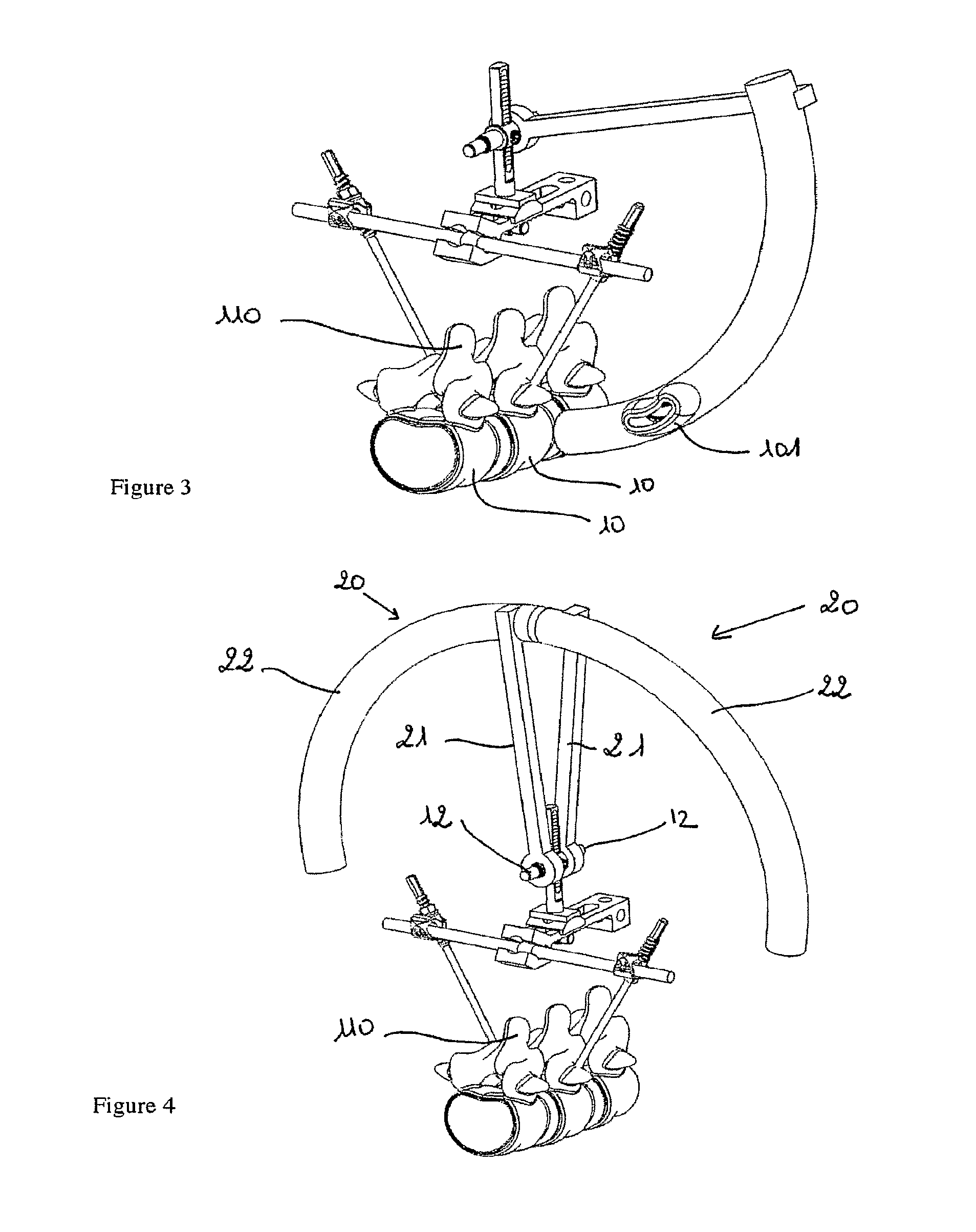
[0023]While referring to FIG. 1, the device 1 is described, which makes it possible to establish an anatomical reference point of an intervertebral disc 100 to be replaced, so as to enable an implantation, through a posterior or posterolateral approach, of a disc prosthesis or an osteosynthesis cage using an adapted implantation instrument. In order to facilitate the understanding of the following discussion, the device 1 for establishing an anatomical reference point of the disc to be replaced will be called “reference point device 1” in the following. The reference point device 1 according to the invention comprises two means for bone anchorage 2, 3 and adjusting elements 4 mounted to be hinged at the proximal ends of the means for bones anchorage 2, 3.

[0024]The adjusting elements 4 comprise a platform 6 provided with a viewing element 5 for the intervertebral disc 100 to be replaced, as well as means for connecting the platform with the first and second means for bone anchorage 2...


PUM


Abstract

The disclosure relates to a device for establishing an anatomical reference point of an intervertebral disc for the attachment of at least one instrument Intended for the implantation, through a posterior or posterolateral approach, of a disc prosthesis or osteosynthesis cage as a replacement for the intervertebral disc. The device includes at least two means for bone anchorage each intended to be attached to a vertebra adjacent to the disc, a coupling element for the instrument and elements for adjusting the position of the coupling element relative to the position of the disc.

Description

CROSS-REFERENCE TO RELATED APPLICATIONS[0001]This application is a continuation of co-pending U.S. application Ser. No. 12 / 997,840, filed Jul. 12, 2011, which is a National Phase Entry of International Application No. PCT / FR2009 / 000704, filed on Jun. 12, 2009, which claims priority to French application Ser. No. 08 / 03314, all of which are incorporated by reference herein.BACKGROUND AND SUMMARY[0002]The invention relates to a device for establishing an anatomical reference point for an intervertebral disc to be replaced by a disc prosthesis or an osteosynthesis cage through posterior or posterolateral approach. The device according to the invention is more particularly, but not exclusively, intended for establishing the anatomical reference point of at least one disc positioned between the lumbar vertebrae L3 and the sacral vertebra S1.[0003]Conventionally, the intervertebral disc is removed and the disc prosthesis is positioned through an anterior or lateral approach of the disc and...

Claims


Application Information

Patent Timeline
Patent Type & Authority Applications(United States)
IPC IPC(8): A61F2/44
CPCA61B2019/2288A61B2019/481A61F2002/4687A61F2002/4668A61F2/4611A61B34/75A61B2090/08021
Inventor PETIT, DOMINIQUEDROULOUT, THOMASAEBI, MAX
Owner NORGINE VENTURES BV
Why Eureka
Try Eureka