Optimal scheduling of venue attendance based on queue size and location

a technology of venue attendance and queue size, applied in the field of managing patron queues, can solve the problems of other customers' dissatisfaction, customer dissatisfaction and corresponding loss of customer participation and revenue, and the efficacy of such policies is limited

Inactive Publication Date: 2012-05-10
IBM CORP
View PDF11 Cites 49 Cited by
  • Summary
  • Abstract
  • Description
  • Claims
  • Application Information

AI Technical Summary

Benefits of technology

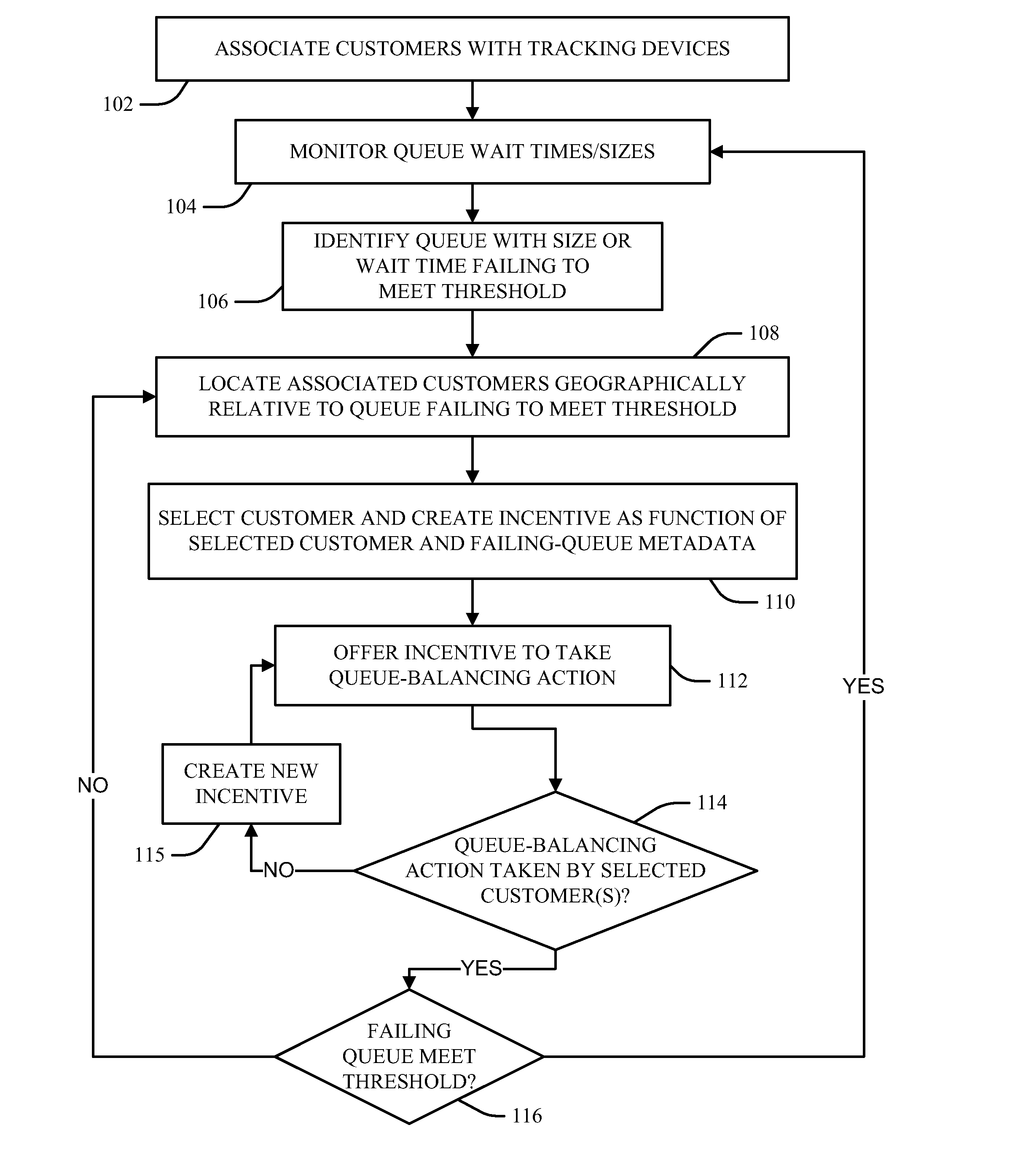
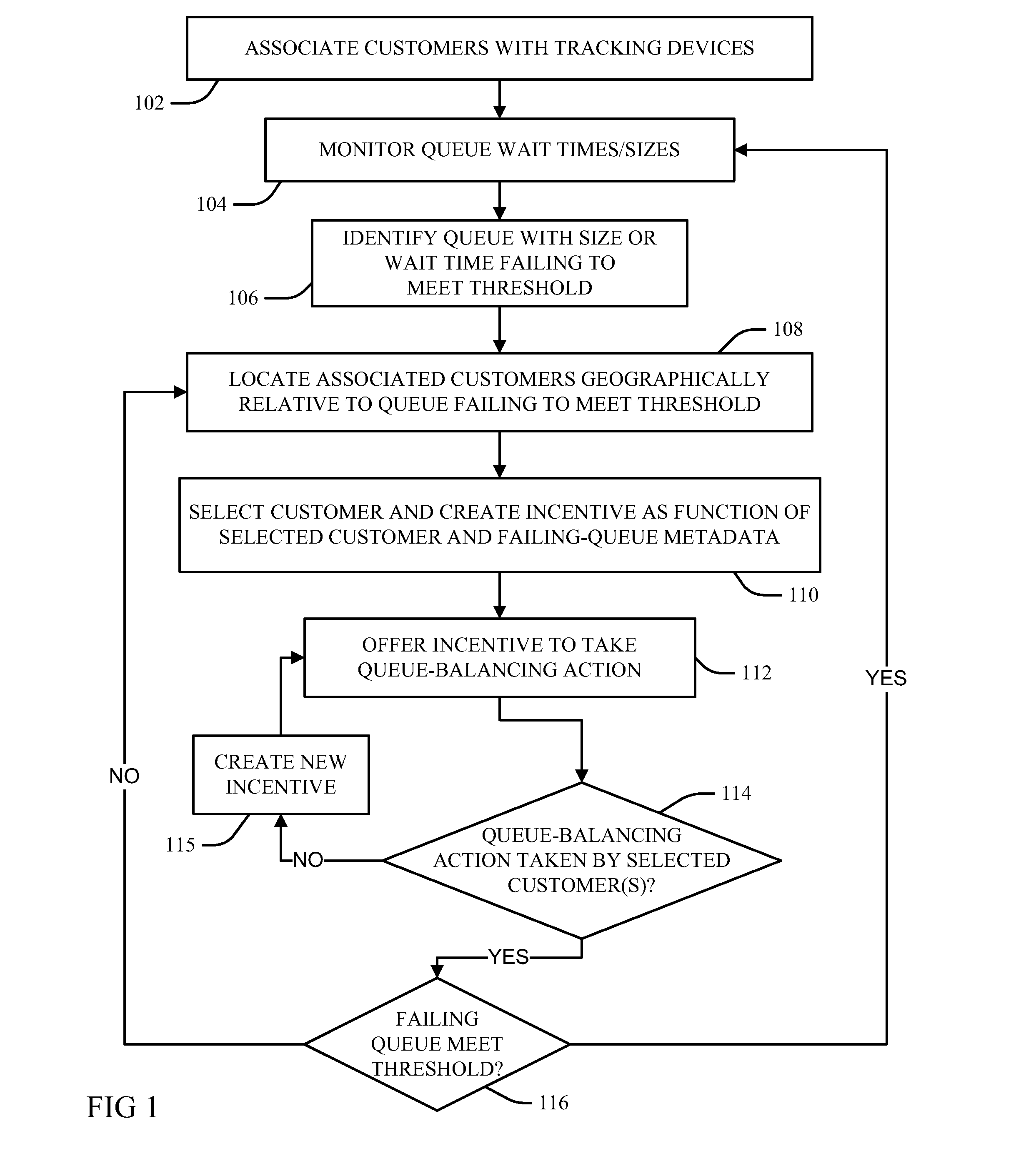
[0004]In one embodiment, a method is provided for managing attraction attendance levels through tracking current attendance levels and notifying patrons of incentives to alter their attraction selections in real-time. The method includes identifying an attraction queue that has a customer wait time failing to meet a threshold and determining a geographic relationship of a tracking device associated with a registered customer to the queue. Accordingly, the method creates an incentive from metadata associated with the queue and offers the incentive to the registered customer to urge the registered customer to take a queue balancing action. The queue balancing action may be leaving the queue if the customer wait time exceeds a threshold maximum wait time and the tracking device is determined to be within the queue, or choosing to enter the queue if the customer wait time is less than a threshold minimum wait time and the tracking device is determined to be outside of the queue.
[0005]I

Problems solved by technology

Queue sizes, which may refer to numbers of patrons or time to serve each patron in the queue (i.e., how long the last person in the queue must wait to be served at the front of the queue) may have fluxes and lulls in the numbers of attending patrons, and thus in corresponding long or short wait times. Long wait times are generally undesired, and may result in customer dissatisfaction and corresponding loss of customer participation and revenue.
However, such techniques generally leave other customers dissat

Method used


Image

  • Optimal scheduling of venue attendance based on queue size and location
  • Optimal scheduling of venue attendance based on queue size and location
  • Optimal scheduling of venue attendance based on queue size and location

Examples


Embodiment Construction

[0012]As will be appreciated by one skilled in the art, aspects of the present invention may be embodied as a system, method or computer program product. Accordingly, aspects of the present invention may take the form of an entirely hardware embodiment, an entirely software embodiment (including firmware, resident software, micro-code, etc.) or an embodiment combining software and hardware aspects that may all generally be referred to herein as a “circuit,”“module” or “system.” Furthermore, aspects of the present invention may take the form of a computer program product embodied in one or more computer readable medium(s) having computer readable program code embodied thereon.

[0013]Any combination of one or more computer readable medium(s) may be utilized. The computer readable medium may be a computer readable signal medium or a computer readable storage medium. A computer readable storage medium may be, for example, but not limited to, an electronic, magnetic, optical, electromagne...


PUM


Abstract

Embodiments of the invention provide for managing attraction attendance levels through tracking current attendance levels and notifying patrons of incentives to alter their attraction selections in real-time. Examples identify an attraction queue that has a customer wait time failing to meet a threshold and determine a geographic relationship of a tracking device associated with a registered customer to the queue. Accordingly, an incentive is created from metadata associated with the queue and offered to the registered customer to urge the registered customer to take a queue balancing action. The queue balancing action may be leaving the queue if the customer wait time exceeds a threshold maximum wait time and the tracking device is within the queue, or choosing to enter the queue if the customer wait time is less than a threshold minimum wait time and the tracking device is outside of the queue.

Description

BACKGROUND[0001]The present invention relates to managing patron queues through influencing patron behaviors by incentives.[0002]More particularly, elements within pubic attractions, such as amusement park rides, museum items, historical sites, etc., often require queues and other limited access strategies to enable each patron to have a turn at enjoying the attraction. Queue sizes, which may refer to numbers of patrons or time to serve each patron in the queue (i.e., how long the last person in the queue must wait to be served at the front of the queue) may have fluxes and lulls in the numbers of attending patrons, and thus in corresponding long or short wait times. Long wait times are generally undesired, and may result in customer dissatisfaction and corresponding loss of customer participation and revenue.[0003]Venue operators sometimes implement preferential admission policies with respect to some customers, for example in order to enable quicker access to the more popular attr...

Claims


Application Information

Patent Timeline
IPC IPC(8): G06Q30/00
CPCG06Q30/0235
Inventor BOSS, GREGORY J.JONES, ANDREW R.MCCONNELL, KEVIN C.MOORE, JR., JOHN E.
Owner IBM CORP
Why Eureka
Try Eureka