
Interlocking device in a vehicle transmission

a technology of interlocking device and transmission shaft, which is applied in the direction of mechanical control device, gearing, instruments, etc., can solve the problems of reducing the number of components, and affecting the operation of the transmission

Active Publication Date: 2012-05-17
VOLVO LASTVAGNAR AB
View PDF17 Cites 2 Cited by
  • Summary
  • Abstract
  • Description
  • Claims
  • Application Information

AI Technical Summary

Benefits of technology

The present invention relates to a device for preventing a certain order of engagement / disengagement of tooth clutches in vehicle transmissions, especially in dual clutch transmissions. The invention aims to prevent blocked shafts and damage to the transmission during shifts. The device includes a control bar, shift rails, springs, and interlocking pins to prevent blocked shafts. The invention also provides a simple and cost-effective solution for preventing blocked shafts in complex transmissions.

Problems solved by technology

This could lead to damage, e.g., broken gear or clutch teeth, and must be prevented.
However, in case of faults, e.g., on sensors and / or valves, blocking of shafts could possibly occur.
Such a design might in addition reduce the number of components, but is, in general, not able to allow as quick shifts as a system with one actuator for each tooth clutch.
That may lead to difficulties in installing the transmission into the vehicle.
However, the tooth clutches on the countershaft make it more difficult to prevent blocking of shafts.
Unfortunately, shift barrels normally only allow sequential shifting, i.e., from one gear to the adjacent higher or lower.
Multi-step shifts are not possible, in general.
That would, however, increase the complexity and cost significantly.
For preventing blocked shafts, mechanical systems that involve more than two tooth clutches tend to be complex, cf.
However, these means only prevent undesirable states of two tooth clutches that would give blocking of shafts.
Said device does not prevent the transmission from being used in a normal way.

Method used


Image

  • Interlocking device in a vehicle transmission
  • Interlocking device in a vehicle transmission
  • Interlocking device in a vehicle transmission

Examples


Embodiment Construction

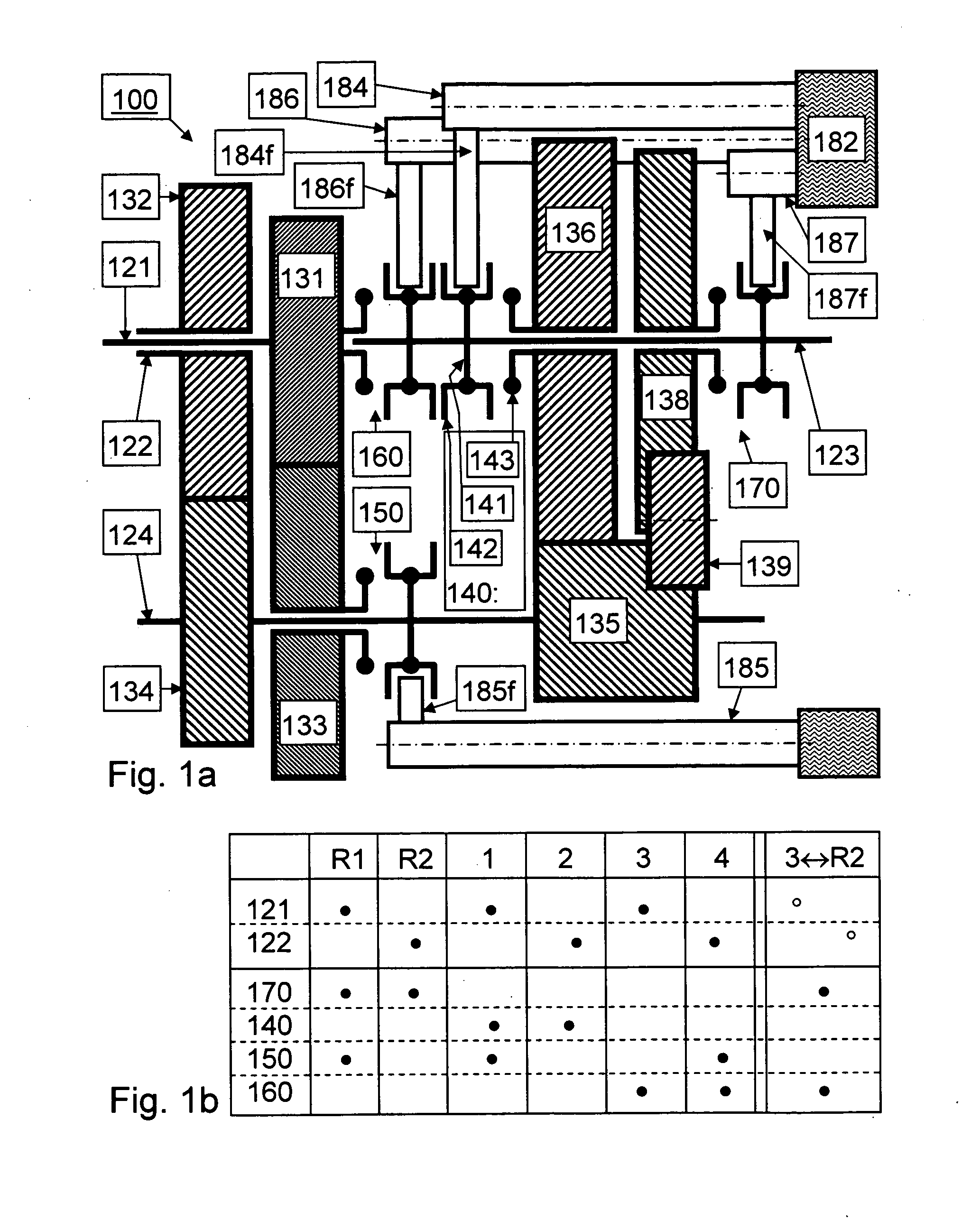
[0030]FIG. 1a shows schematically a dual clutch main transmission 100. There is a first input shaft 121 and a coaxial second input shaft 122. Each of those input shafts can be drivably connected to a prime mover by a dual frictional clutch unit (not shown). A main and output shaft 123 is arranged coaxial to input shafts 121 and 122. A countershaft 124 is arranged parallel thereto.

[0031]A first input shaft gearwheel 131 is integral or rotationally fixed with the first input shaft 121. Similarly, a second input shaft gearwheel 132 is integral or rotationally fixed with the second input shaft 122. The first input shaft gearwheel 131 is in mesh with a primary countershaft loose gearwheel 133 that is arranged on the countershaft 124. A second countershaft primary gearwheel 134 is integral or rotationally fixed with the countershaft 124 and in mesh with the second input shaft gearwheel 132. A countershaft secondary gearwheel 135 is integral or rotationally fixed with the countershaft 124 ...


PUM


Abstract

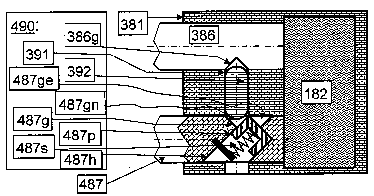
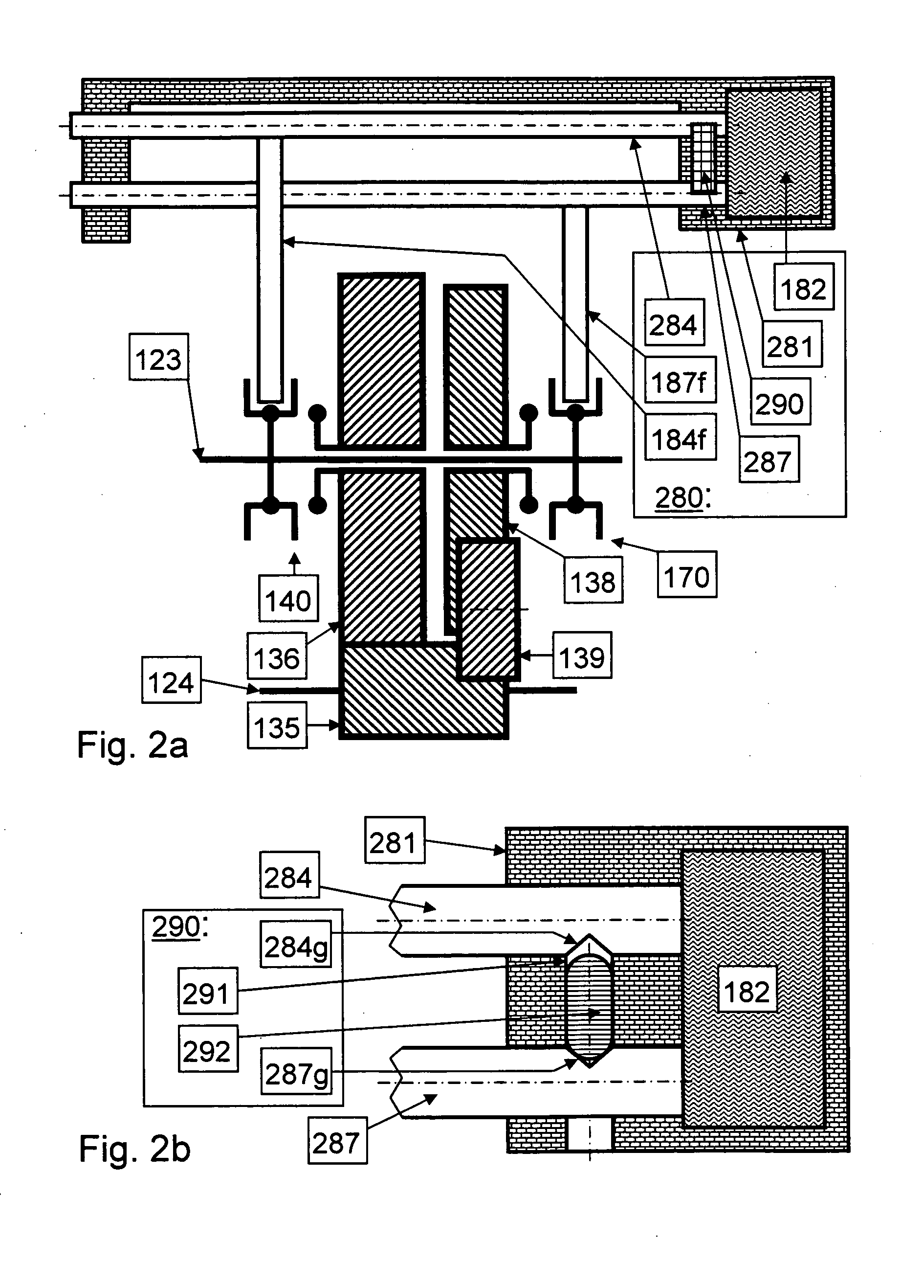
An interlocking device arranged to prevent forbidden order of engagement / disengagement of two tooth clutches in a vehicle transmission is provided and includes a groove arranged in a first of shift rods, and a second and a third groove arranged in a second of shift rods, an interlocking element arranged coplanar with the shift rods, and directed and movable towards the shift rods. The length of the interlocking element is adapted to allow certain combinations and order of engagement / disengagement of the tooth clutches. A piston element partitions the second and third groove. The piston element is movably arranged in a hole in the second shift rod such that the interlocking element can push the piston element down in the hole, allowing the second shift rod to be displaced only one-way when the first shift rod is in an engaged position.

Description

BACKGROUND AND SUMMARY[0001]The present invention relates to vehicle transmissions, especially with automatic gear shifting, and more particularly to a device for preventing a certain order of the engagement / disengagement of tooth clutches.[0002]The conventional stepped transmission for rear-wheel drive vehicles can be regarded as a robust, compact and cost-effective product. A typical example of such a lay-out is shown in FIG. 2 in DE10242823A1. An input shaft is coaxial with a main (output) shaft and parallel with a countershaft. A gearwheel that is rotationally fixed on the input shaft meshes with a gearwheel that is rotationally fixed on the countershaft. Several pairs of meshing gearwheels are then located side by side. In each of these pairs, one gearwheel is coaxial with the countershaft; the other is coaxial with the main shaft. One of these gearwheels is rotationally fixed on its coaxial shaft. The other gearwheel, the loose gearwheel, is free to rotate relative to its coax...

Claims


Application Information

Patent Timeline
Patent Type & Authority Applications(United States)
IPC IPC(8): G05G5/08
CPCF16H3/006F16H3/0915F16H61/688Y10T74/2011F16H2063/3079F16H2312/08F16H63/36Y10T74/19219Y10T74/19251
Inventor BERGSTROM, KLASHEDMAN
Owner VOLVO LASTVAGNAR AB
Learn More