Stabilizing mechanism and method for a stowed mobile satellite reflector antenna

a mobile satellite reflector and stabilizer technology, applied in the direction of machine supports, collapsible antennas, shock absorbers, etc., can solve the problems of large reflectors, bounce and move, large reflectors, etc., to minimize the damage of the reflector antenna, maintain a separation distance, and minimize movement

Inactive Publication Date: 2012-05-17
WINEGARD
View PDF0 Cites 0 Cited by
  • Summary
  • Abstract
  • Description
  • Claims
  • Application Information

AI Technical Summary

Benefits of technology

[0006]A stabilizing mechanism for a reflector antenna, in a mobile satellite system mounted to a vehicle or mounted in a container, is provided to substantially minimize damage to the reflector antenna when stowed. The stabilizing mechanism uses a pair of stabilizing surfaces connected on opposite sides of the reflector antenna. A first end of each stabilizing device is connected on one of the opposing sides of the reflector antenna. The second end of each stabilizing device abuts, with a pre-load force, against a corresponding stabilizing surface in said pair of stabilizing surfaces when said reflector antenna is stowed. The stabilizing surface may be on the system, the mount for the system, or the vehicle or container transporting the system. The pre-loaded abutment minimizes any movement of the reflector antenna towards the stabilizing surface during transport or in adverse environmental conditions.
[0007]A method protecting a stowed reflector antenna in a mobile satellite antenna system encountering mechanical stress during transport. The method includes abutting a pair of stabilizing devices connected to opposite sides of the stowed reflector antenna against a stabilizing surface. The method further includes minimizing movement between the stabilizing surface and the stowed reflector antenna when the mobile satellite system encounters mechanical stress. The method further includes pre-loading the stabilizing devices against the stabilizing surface. The method also includes maintaining a separation distance between the reflector antenna and the stabilizing surface.

Problems solved by technology

These systems need to be rugged and reliable, are often transported through difficult terrain and are subjected to severe weather environments.
Such large reflectors when stowed can bounce and move.
The damage can occur to either or both the reflector antenna and to the transport surface.

Method used


Image

  • Stabilizing mechanism and method for a stowed mobile satellite reflector antenna
  • Stabilizing mechanism and method for a stowed mobile satellite reflector antenna
  • Stabilizing mechanism and method for a stowed mobile satellite reflector antenna

Examples


Embodiment Construction

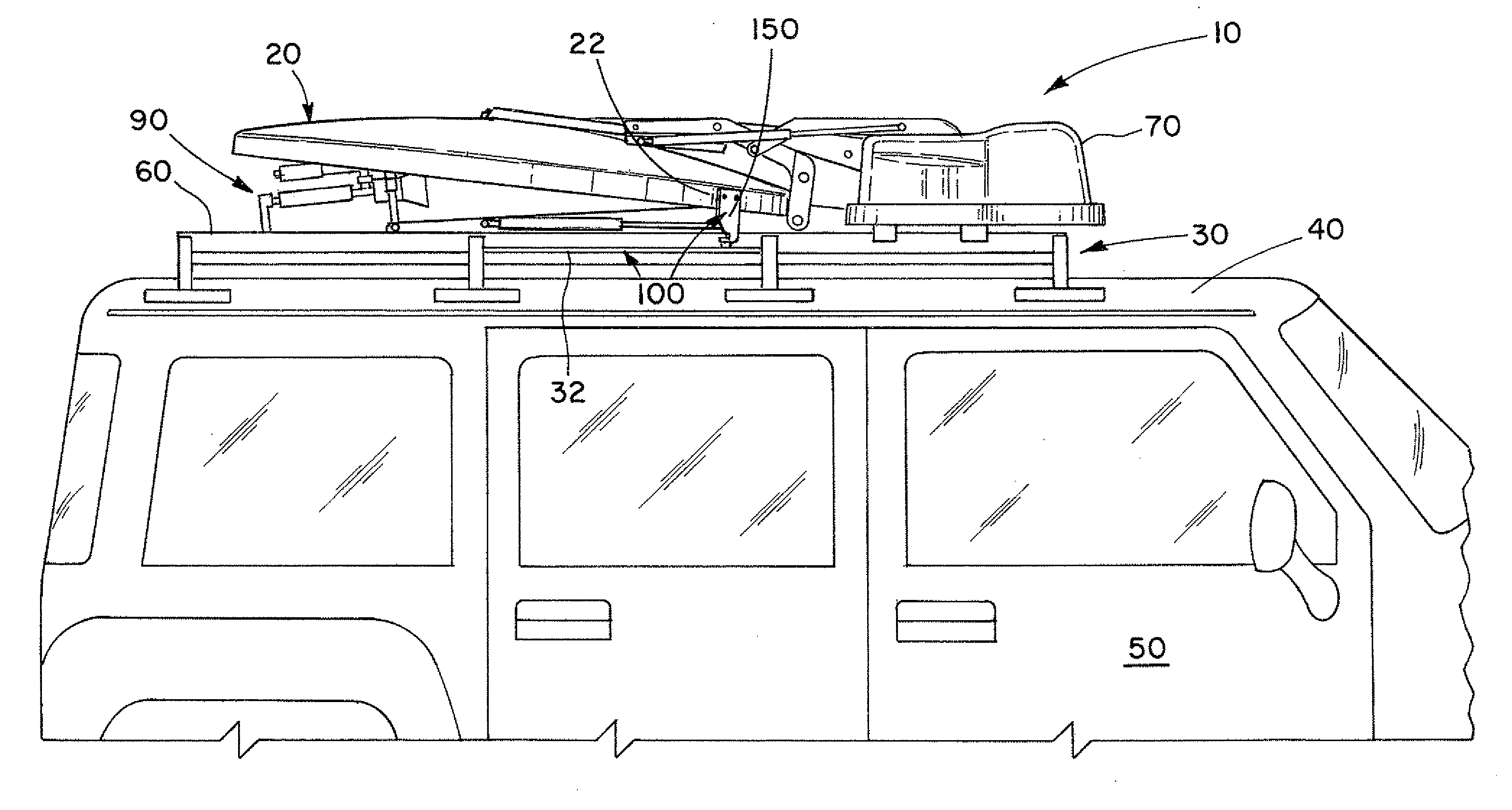
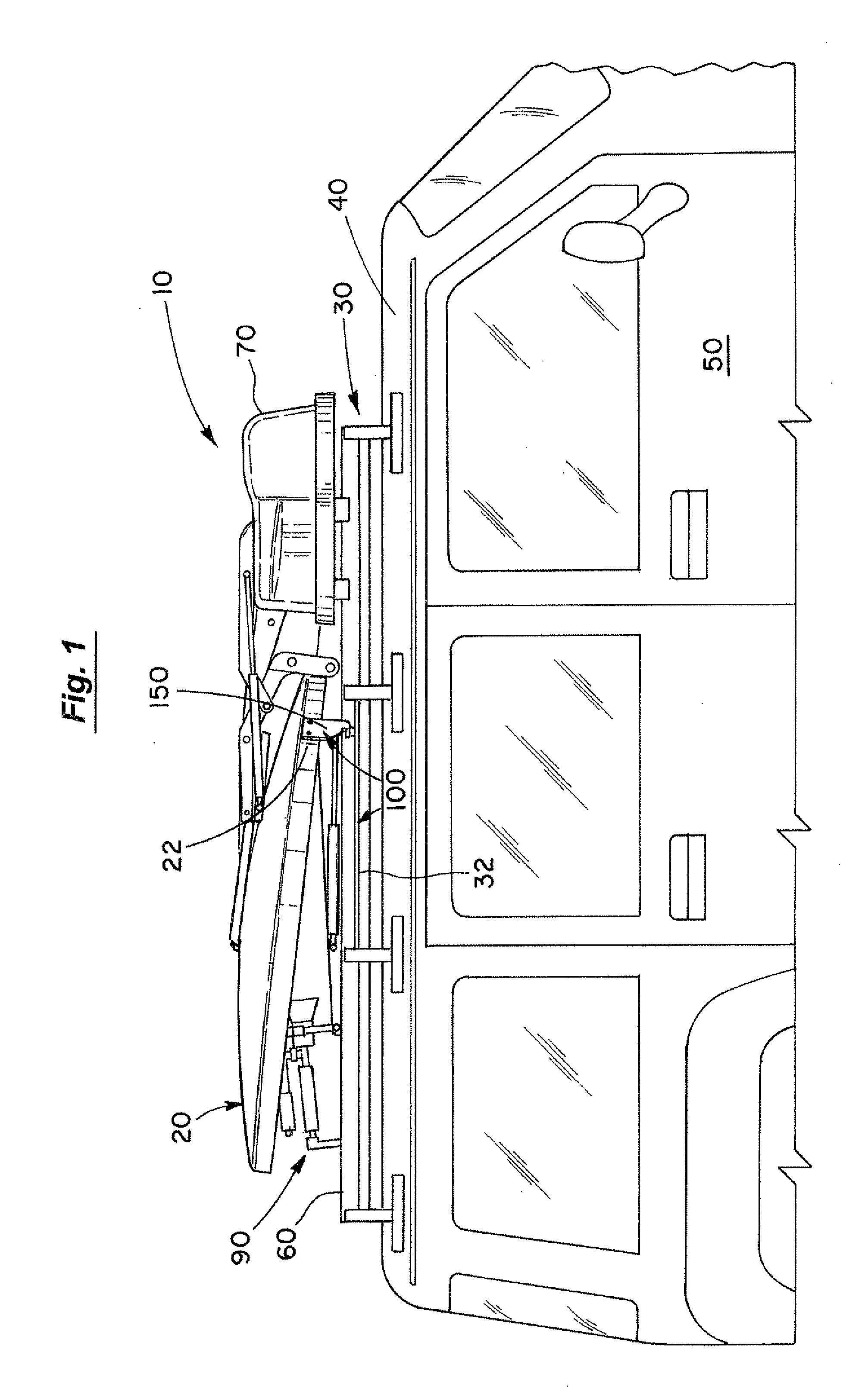
[0025]In FIG. 1, the mobile satellite system 10 of the present invention is shown, with the reflector antenna 20 in a stowed position, on a conventional mount 30 on an upper surface 40 of a vehicle 50. The vehicle 50 can be any suitable vehicle such as a truck, van, SUV, trailer, RV, marine vessel, transport, etc. The mobile satellite system 10 may also be conventionally mounted in a container (not shown).

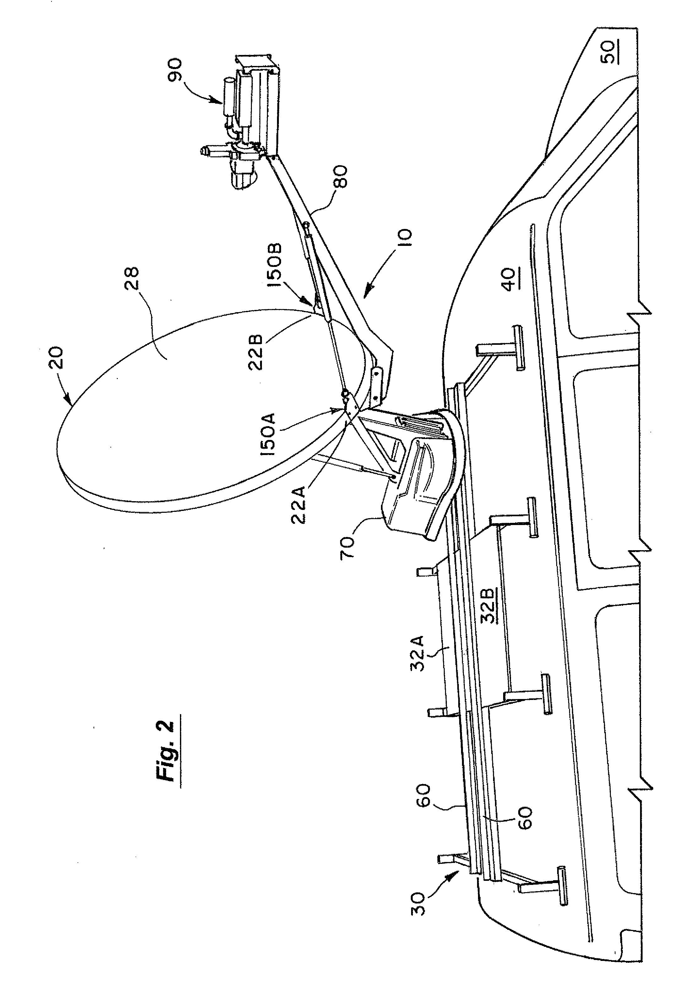
[0026]FIG. 2 shows the reflector antenna 20 deployed and targeted on a desired orbiting satellite (not shown). The mobile satellite system 10 of FIGS. 1 and 2 conventionally has a pair of tracks 60 on a mount 30 on the vehicle surface 40; a housing 70 containing motors, gears, controls (all not shown); and a feed support arm 80 carrying a feed 90. The mount 30, in one embodiment, has opposing plates on opposite sides of the mount 30 which form a pair of stabilizing surfaces 32A, 32B. In another embodiment, the stabilization surface 32 is provided by the roof 40 of the vehicle 50 (o...


PUM

PropertyMeasurementUnit
sizeaaaaaaaaaa
temperatureaaaaaaaaaa
pre-load forceaaaaaaaaaa

Abstract

A stabilizing mechanism and method for a reflector antenna, in a mobile satellite system on a transport, such as a vehicle, for substantially minimizing damage to the reflector antenna when stowed. The stabilizing mechanism uses a stabilizing surface and a pair of stabilizing devices connected on opposite sides of the reflector antenna to provide a pre-load separation distance between a stabilizing surface and the reflector antenna when the reflector antenna is stowed. The pre-loaded separation minimizes any movement of the reflector antenna towards the stabilizing surface during movement of the transport or in adverse environmental conditions.

Description

BACKGROUND OF THE INVENTION[0001]1. Field of the Invention[0002]The invention relates to the field of mobile satellite reflector systems and, more particularly, to mechanisms and methods for stabilizing stowed reflector antenna in mobile satellite systems so as to minimize damage under adverse environmental conditions or during movement of a transport carrying the mobile satellite system.[0003]2. Discussion of the Background[0004]Mobile satellite systems, mounted on a wide variety of vehicles, are used worldwide to provide two-way satellite communications such as, for example, broadband data, video conferencing and other corporate communications for such diverse uses such as, for example, found for oil and gas exploration, construction, military, mobile education, emergency medical and service providers, and news organizations. These systems need to be rugged and reliable, are often transported through difficult terrain and are subjected to severe weather environments. In use, the m...

Claims


Application Information

Patent Timeline
Patent Type & Authority Applications(United States)
IPC IPC(8): B60R11/00F16F7/00B23P17/04F16M13/00
CPCH01Q1/08Y10T29/49826H01Q15/161H01Q1/3275
Inventor CONRAD, TIMOTHY JOHN
Owner WINEGARD
Why Eureka
Try Eureka