Eureka AIR delivers breakthrough ideas for toughest innovation challenges, trusted by R&D personnel around the world.

Locating Devices in a Wireless Network

Active Publication Date: 2012-05-17
HEWLETT-PACKARD ENTERPRISE DEV LP
View PDF3 Cites 25 Cited by
  • Summary
  • Abstract
  • Description
  • Claims
  • Application Information

AI Technical Summary

Problems solved by technology

Determining the location of a wireless device is an old problem.

Method used


Image

  • Locating Devices in a Wireless Network
  • Locating Devices in a Wireless Network
  • Locating Devices in a Wireless Network

Examples


Embodiment Construction

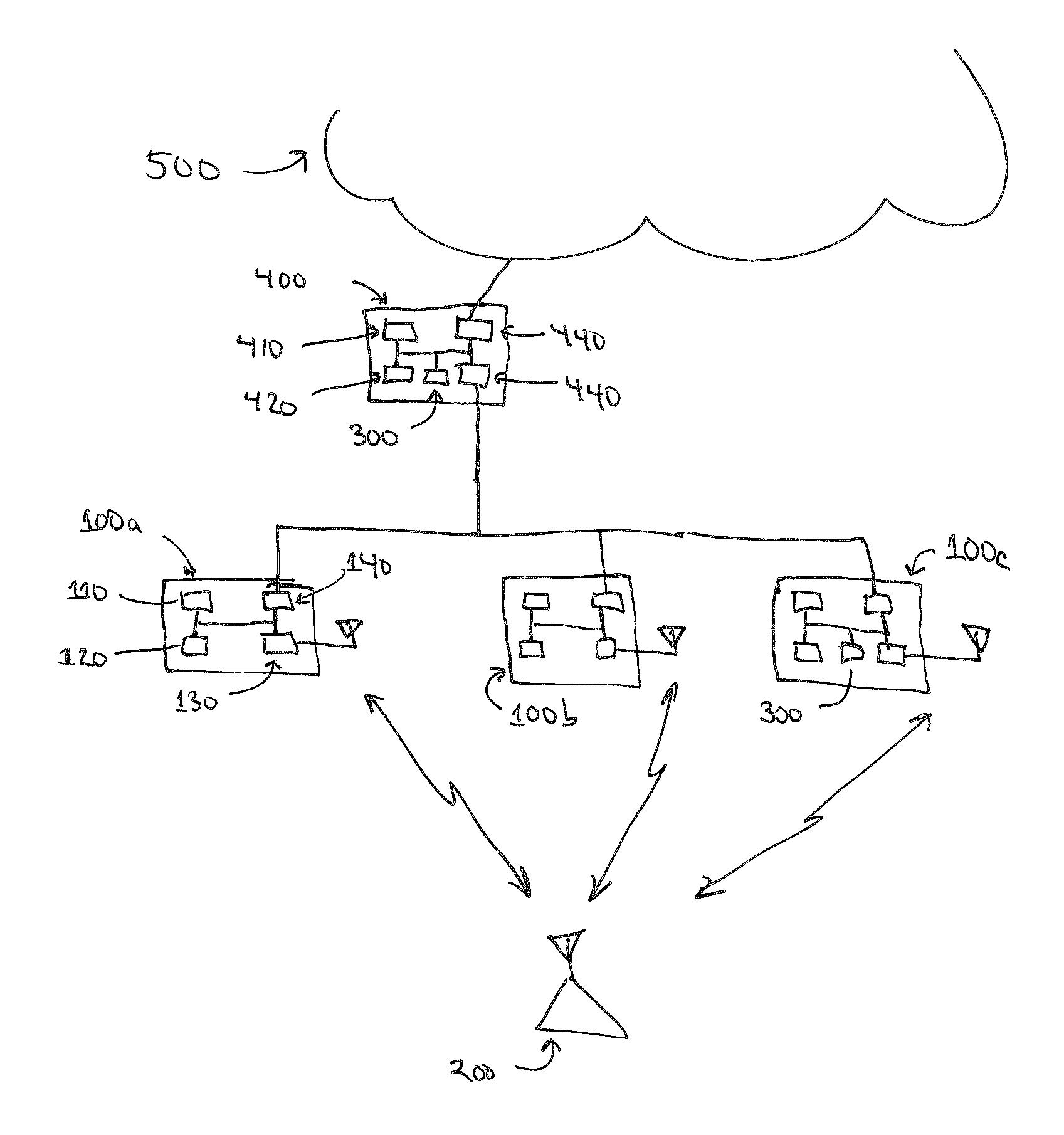
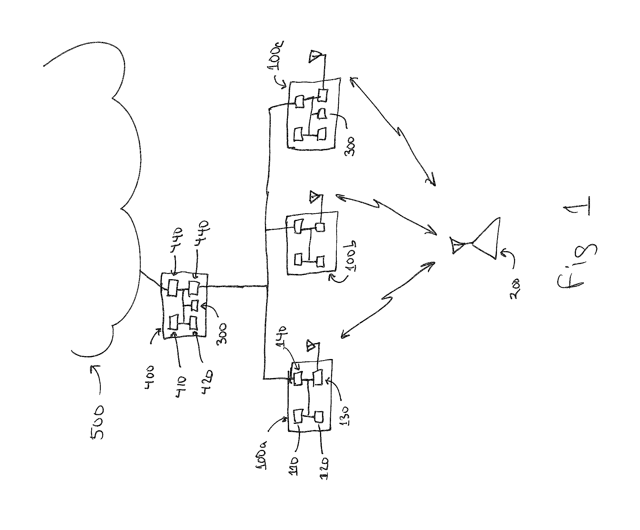
[0009]Embodiments of the invention relate to methods of estimating the location of a wireless device operating in the range of a wireless digital network.

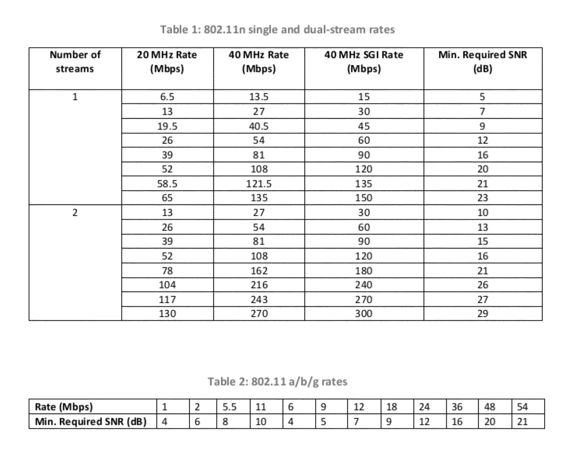
[0010]According to the present invention, a locating device (LD) attached to a network transmits frames to a device to be located (DTL) and receives an Acknowledgement (ACK) response when the frame has been received by the DTL without error. The LD varies transmission parameters of the frames transmitted to the DTL, looking for a change in the failure rate of the ACKs received from the DTL. Transmission parameters varied by the LD include transmit power, attenuation and transmit data rate. The LD searches this transmission parameter space looking for the critical level where the DTL goes from not being able to receive the frame to being able to successfully receive and acknowledge the frame. Since the signal level at the DTL to successfully decode a frame with a given set of parameters is known, and the transmit path and therefore ...


PUM


Abstract

Determining the location of a wireless device to be located (DTL) by three or more locating devices (LDs). LDs operating at known locations estimate the distance to the DTL by sending wireless frames to the DTL and varying frame parameters such as transmit power and data rate, searching for the boundary at which the frame is or is not received and ACKd by the DTL. For a given set of frame parameters, the SNR required to be successfully received at the DTL is known. Given that the configuration of the LD is known, the EIRP of the DL is also known. Estimating the noise floor at the DTL, and using the SNR required to successfully receive the frame at the DTL and the EIRP at the LD transmitting the frame, the path loss can be calculated. From the path loss and operating frequency, a distance estimate is calculated. EIRP of the DTL is not and need not be known. Distance estimates from at least three LDs at known locations allow a location for the DTL to be calculated by a location engine (LE). Distance estimates from more than three LDs allow for an overdetermined solution. Distance estimates derived in this manner may be combined with distance estimates calculated using other approaches, such as measuring signal strengths, or TOA / TDOA measurements. The LE process may reside on a central controller supporting the LDs, on one of the LDs, or on any suitable device with network access.

Description

BACKGROUND OF THE INVENTION[0001]The present invention relates to wireless digital networks, and in particular, to the problem of locating a wireless device.[0002]Determining the location of a wireless device is an old problem. Typical solutions rely on a number (greater than two) of locating devices (LD) at known locations. Each LD makes a measurement of some characteristic of a signal from the device to be located (DTL), where the measurement correlates to a distance estimate between the DT and the LD. Using distance estimates and locations from three LDs, a location for the DTL may be calculated. Using distance estimates and locations from more than three LDs, an overdetermined location for the DTL may be calculated.[0003]One measurement which may be made by the LDs is the time of arrival of a signal transmitted by the DTL. As an example, LDs may time stamp the arrival of a particular part of a known frame transmitted by the DTL. To derive an accurate location, these time stamps ...

Claims


Application Information

Patent Timeline
IPC IPC(8): G08B5/22
CPCG01S5/00H04W24/00G01S11/06G01S5/14
Inventor PONNUSWAMY, SUBBURAJAN
Owner HEWLETT-PACKARD ENTERPRISE DEV LP
Why Eureka
Eureka Blog
Learn More