
Efficient active multi-drive radiator

a radiator and active driver technology, applied in the direction of antennas, non-resonant long antennas, electric long antennas, etc., can solve the problems of low optimal load impedances from the perspective of active drivers, crowded spectrum at lower frequencies, and ineffective traditional power transfer methods to off-chip loads (e.g., external antennas) , to achieve the effect of low optimal load impedances

Active Publication Date: 2015-12-29
CALIFORNIA INST OF TECH
View PDF53 Cites 6 Cited by
  • Summary
  • Abstract
  • Description
  • Claims
  • Application Information

AI Technical Summary

Benefits of technology

The invention is a multi-port driven antenna that has a conductor and can radiate electromagnetic radiation. It has multiple input ports with electrical connections to the antenna at different locations along its length. Each input port has a signal input terminal that receives an input signal with a predetermined phase relationship to another input signal. The antenna structure is designed to radiate millimeter wave electromagnetic radiation. The invention also includes a source of input signals and an amplifier to amplify the input signals. The multi-port driven antenna can be used in a phased array configuration. The method of generating electromagnetic radiation involves applying input signals with a predetermined phase relationship to the antenna. The technical effects of the invention include improved signal-to-noise ratios, improved spatial resolution, and improved millimeter wave electromagnetic radiation coverage.

Problems solved by technology

This has caused the spectrum at lower frequencies to become crowded.
However, integrated power generation and particularly radiation present several challenges ranging from on-chip power combining and impedance matching to off-chip power transfer.
The traditional power transfer methods (e.g., bonding wires and solder balls or solder bumps) to off-chip loads (e.g., external antenna) also become increasingly ineffective.
The low breakdown voltages of integrated silicon transistors encourages the use of large transistors or highly parallel transistors for high power generation, leading to low optimal load impedances from the active driver's perspective.
Unfortunately, this directly conflicts with single-port antenna impedance level trade-offs, where a large radiation resistance compared to the loss resistance is preferred for high efficiency.
Among the disadvantages of the traditional approach at these frequencies are the losses incurred in transmission lines and interconnects and the low gain available in amplifier stages.
Impedance matching networks on chip often can induce several dB of loss, and efficient inteconnects to an off chip-board or cable are not feasable or rugged enough for mass production.

Method used


Image

  • Efficient active multi-drive radiator
  • Efficient active multi-drive radiator
  • Efficient active multi-drive radiator

Examples


first embodiment

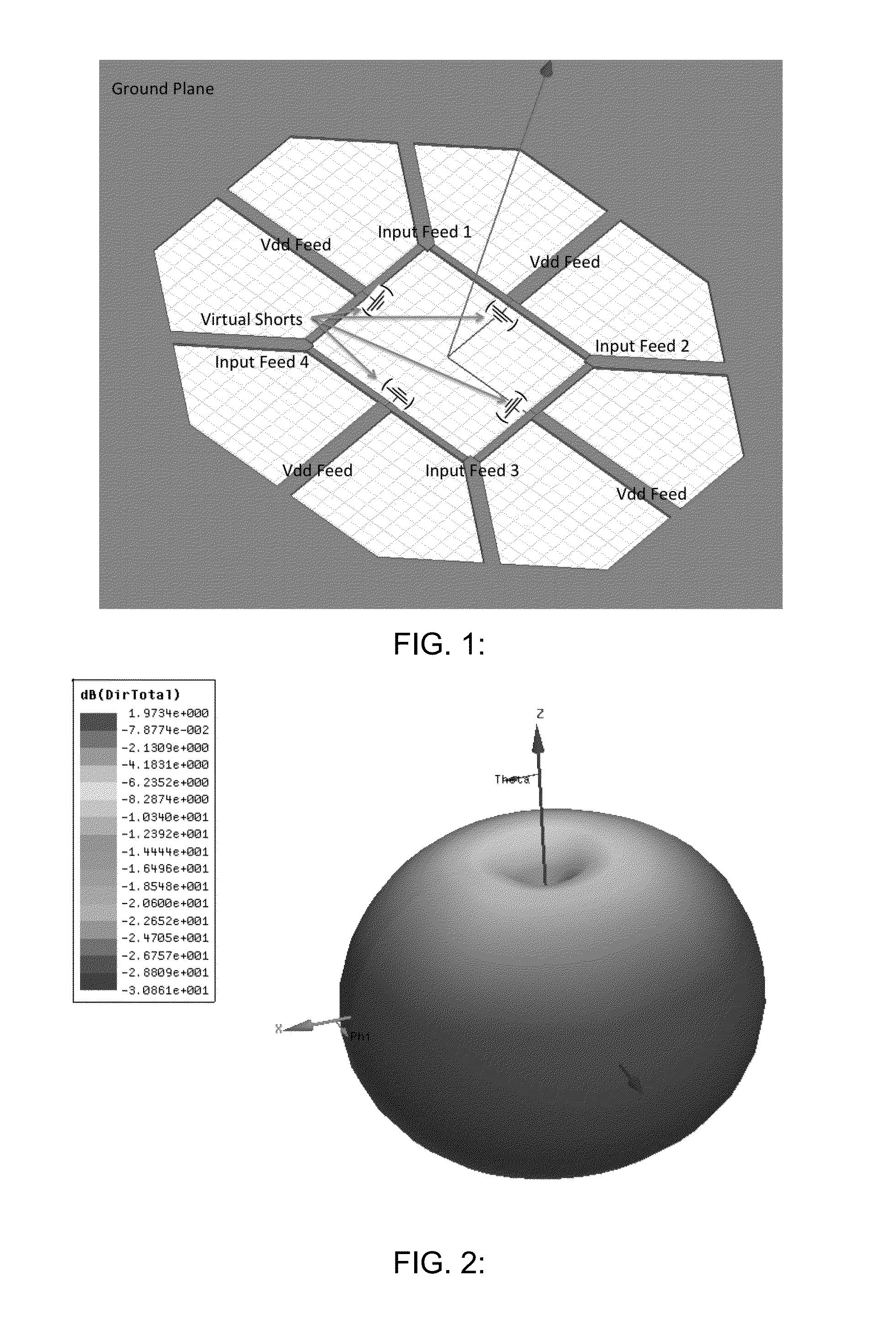
[0058]In one embodiment (First Embodiment), a loop MPD radiator has multiple input terminals spaced apart along the loop, all of which input terminals are driven with differential feeds, all of which have the same phase. An example of such a radiator is illustrated in FIG. 1.

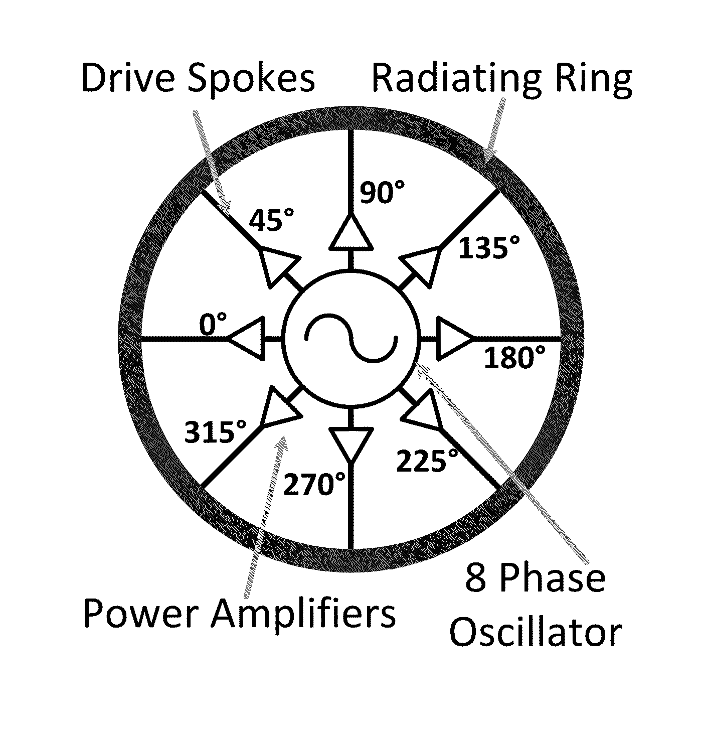
[0059]In still another embodiment, a design termed a differential radial MPD radiator has a loop conductor with a plurality S of differential feeds which span a phase space of 2Nπ, where N is an integer, and each feed has a phase shift of 2πN / S compared to each of the two adjacent feeds. Embodiments of this type of MPD radiator are shown in FIG. 8 and FIG. 11. The First Embodiment described above can be considered as a special case of this type of MPD radiator, with the condition that N=0.

[0060]In a further embodiment, termed a single ended radial MPD radiator, a loop conductor has a plurality S of single-ended feeds which span a phase space of 2Nπ, where N is an integer, and each feed has a phase shift of 2πN / S...

second embodiment

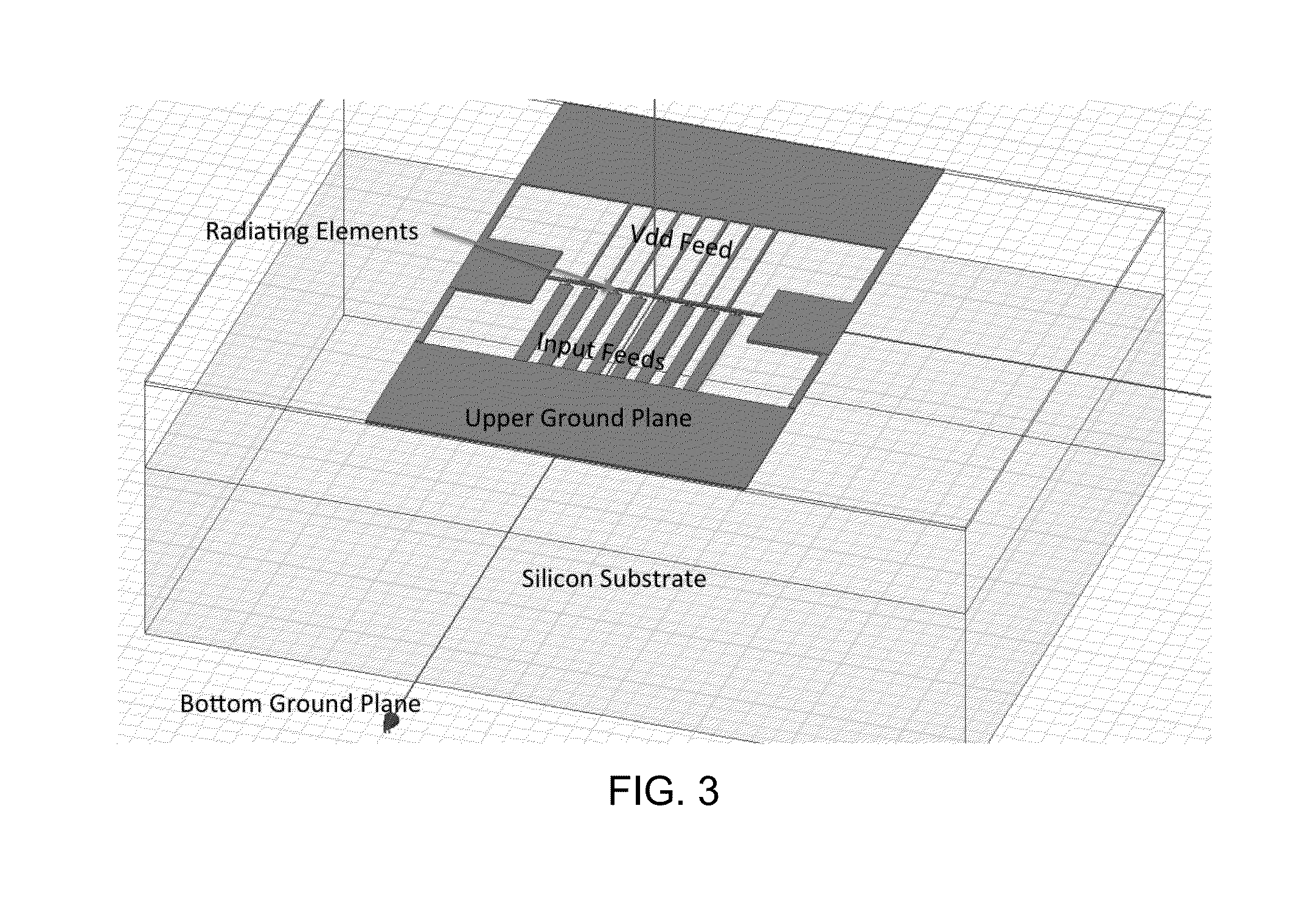
[0092]FIG. 11 is a schematic diagram of a differential radial multi-port driven radiator in a loop topology. The embodiment of FIG. 11 includes a ground plane and DC power / input signal feeds. This structure could either have a ground plane on the bottom to facilitate front-side radiation, or could leave the backside open and radiate in that direction. For the following plot, backside radiation is considered.

[0093]FIG. 12 is a three dimensional plot of the radiation pattern emitted by an active multidrive radiator in a loop topology. The radiation pattern of FIG. 12 shows a broad beam that is appropriate for putting into a phased array. Such an array of these devices would allow for beam steering with the addition of phase shifters between loops. It has also been observed that traveling, circularly polarized waves do not create nearly as much substrate loss as standing waves that are linearly polarized. This effect can be used to increase the efficiency of such a structure.

[0094]Thes...


PUM


Abstract

An integrated Multi-Port Driven (MPD) antenna that can be driven at many points with different signals. An integrated MPD radiating source utilizing an 8-phase ring oscillator and eight power amplifiers to drive the MPD antenna at 161 GHz with a total radiated power of −2 dBm and a single element EIRP of 4.6 dBm has been demonstrated in silicon with single lobe well behaved radiation patterns closely matching simulation.

Description

CROSS-REFERENCE TO RELATED APPLICATIONS[0001]This application claims priority to and the benefit of U.S. provisional patent application Ser. No. 61 / 548,665 filed Oct. 18, 2011, which application is incorporated herein by reference in its entirety.STATEMENT REGARDING FEDERALLY FUNDED RESEARCH OR DEVELOPMENT[0002]This invention was made with government support under FA8650-09-C-7924 awarded by USAF / ESC. The government has certain rights in the invention.FIELD OF THE INVENTION[0003]The invention relates to antennas or radiators in general and particularly to an on-chip antenna or radiator.BACKGROUND OF THE INVENTION[0004]Wireless communication continues to increase in popularity, driving up the demand for wireless bandwidth. This has caused the spectrum at lower frequencies to become crowded. The need to be able to utilize additional spectrum at higher millimeter-wave frequencies has become critical. At the same time, the maximum operating frequencies of transistors, fmax, for example ...

Claims


Application Information

Patent Timeline
Patent Type & Authority Patents(United States)
IPC IPC(8): H01Q11/04H01Q25/04
CPCH01Q25/04H01Q11/04H01Q1/48
Inventor BOWERS, STEVENHAJIMIRI, SEYED ALI
Owner CALIFORNIA INST OF TECH
Learn More