Methods for designing lobe-type rotors

a rotor and lobe technology, applied in the direction of liquid fuel engines, process and machine control, instruments, etc., can solve the problems of increased wear, abnormal situations such as noise and vibration, and the curvature of each lobe of the rotor is not continuously and smoothly contacted, so as to achieve a larger discharge capacity, secure a smooth process, and improve the effect of compression ratio

Active Publication Date: 2007-03-01
LIUNG FENG INDAL
View PDF1 Cites 2 Cited by
  • Summary
  • Abstract
  • Description
  • Claims
  • Application Information

AI Technical Summary

Benefits of technology

[0007] Accordingly, an object of the present invention is to provide a method for designing lobe-type rotors which is able to generate a defined rotor and a conjugate rotor with three or more than three lobes intermeshing and conjugating to each other by different parameters. Moreover, the m...

Problems solved by technology

The rotors of the prior arts have drawbacks that curves of each lobe of the rotors are not continuously and smoothly contacted at the joint between each segment; such drawbacks cause tips of the rotors do not mesh completely with other rotor when they are rotating.
Consequently, in applying to machines working as pe...

Method used


Image

  • Methods for designing lobe-type rotors
  • Methods for designing lobe-type rotors
  • Methods for designing lobe-type rotors

Examples


Embodiment Construction

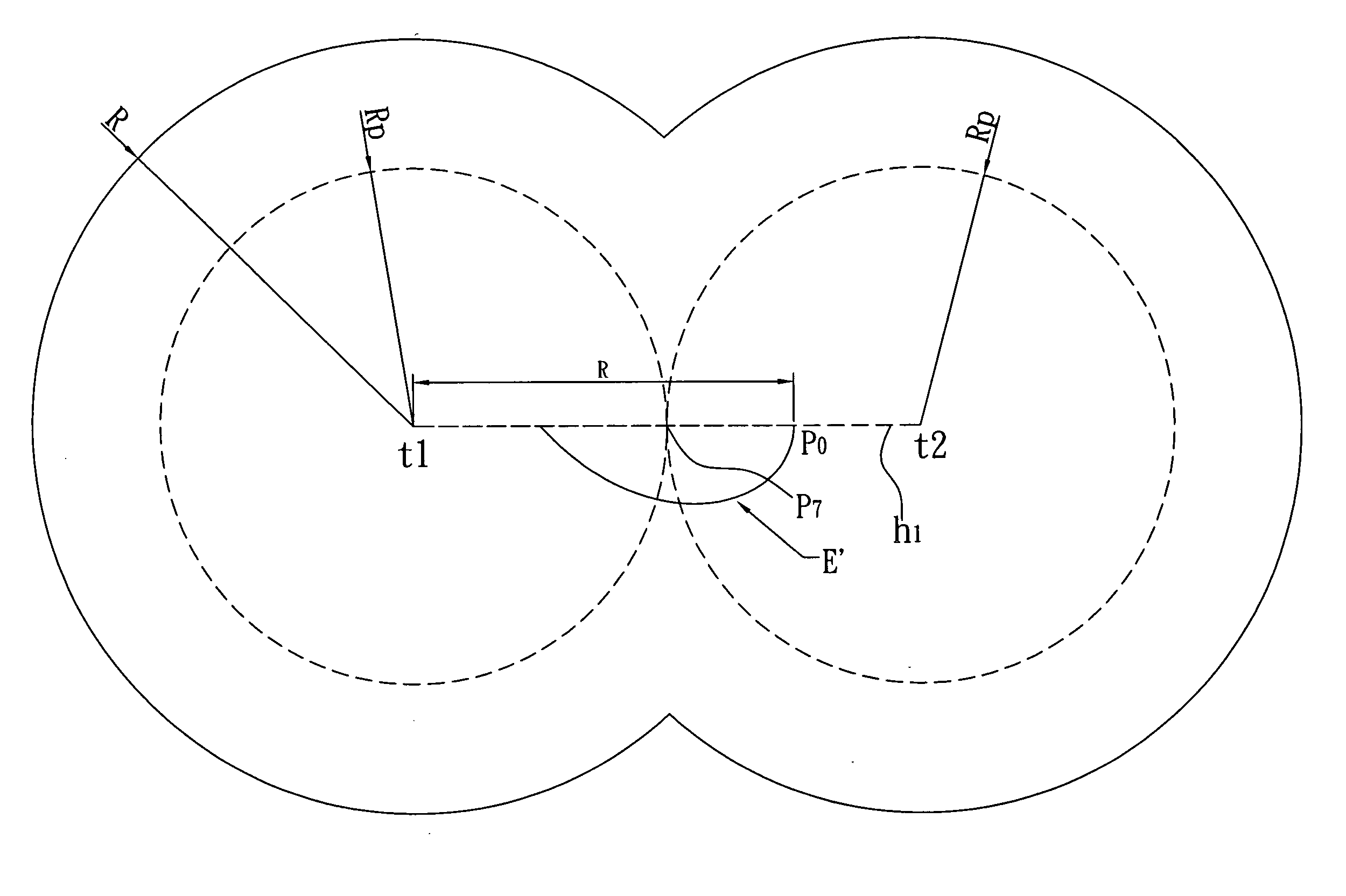
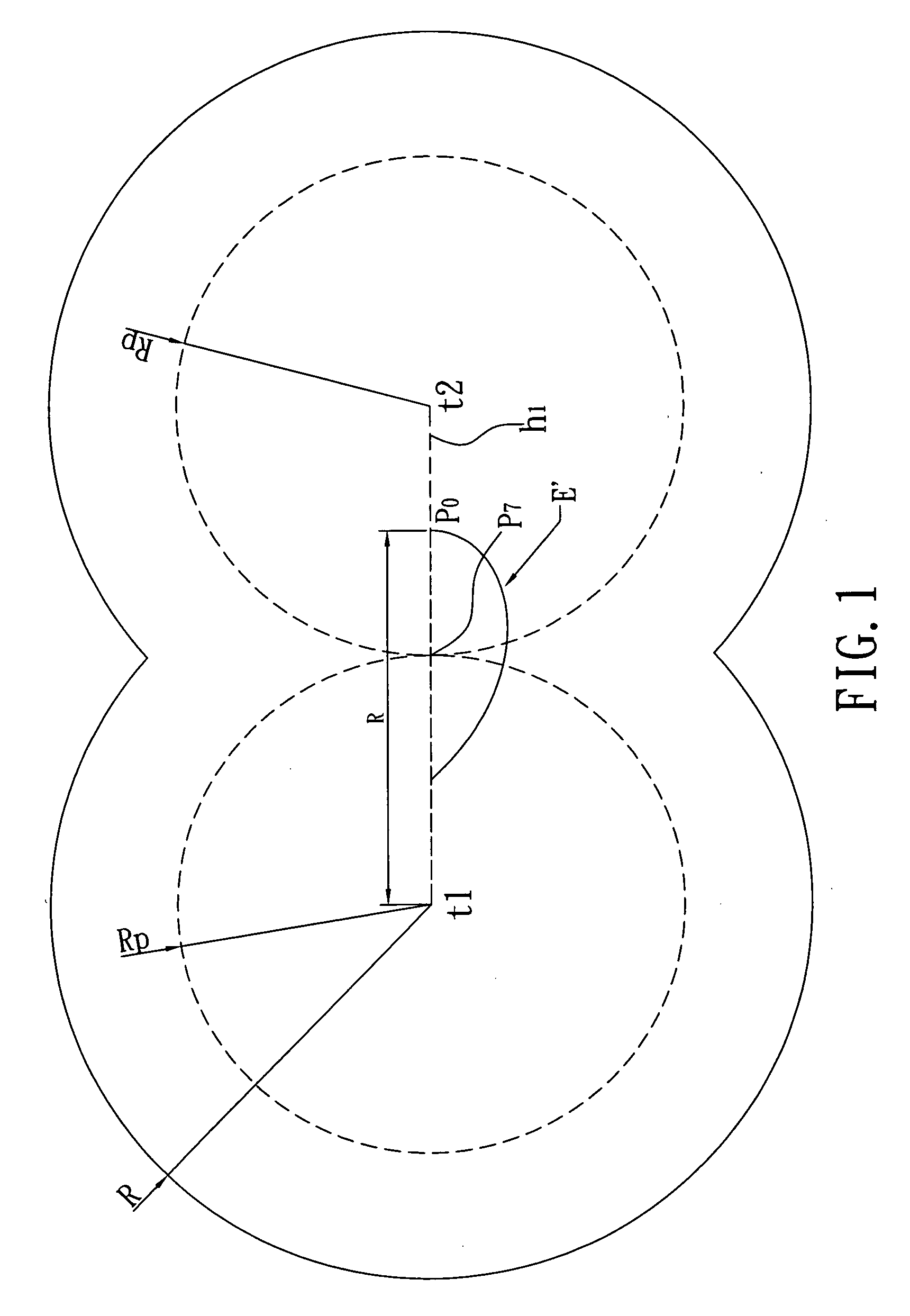
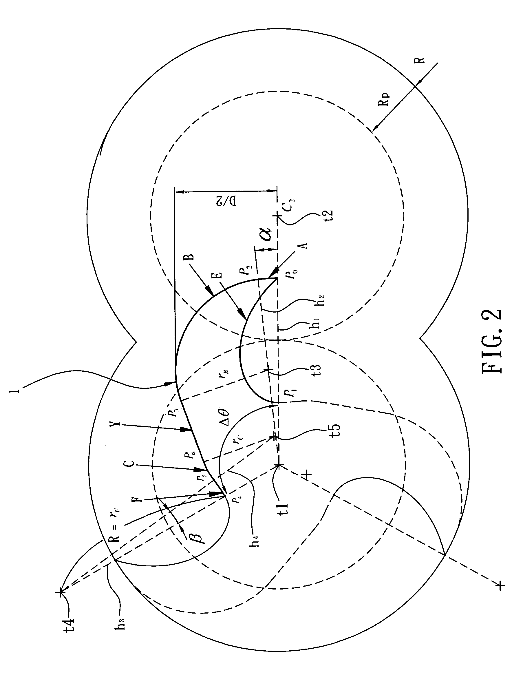
[0015] A three-lobe or more than three-lobe rotor design process in accordance with the present invention is adapted for designing curve portions of a defined rotor 1 by suitable parameters, and then get the curve portions of a conjugate rotor 2 with conjugate theory. Referring to FIGS. 1 to 3, designing process for forming the curve portions of the defined rotor 1 comprises the following steps: [0016] 1. Designate a maximum radius R and a width D of the defined rotor 1, a pitch circle radius Rp of the defined and the conjugate rotor 1, 2, a first center t1 of the defined rotor 1 and a second center t2 of the conjugate rotor 2, wherein R=60 mm, D=65 mm, Rp=40 mm, the pitch circle radius Rp is smaller than radius R, and R and Rp are in appropriate ratio R=3 Rp / 2. [0017] 2. Referring to FIG. 1, define a reference horizontal line h1 by straight connecting the first center t1 and the second center t2, a base point P0 located on the reference horizontal line h1 and being offset from the ...


PUM

PropertyMeasurementUnit
Radiusaaaaaaaaaa

Abstract

The present invention provides a method for designing lobe-type rotors which enables a defined rotor and a conjugate rotor with three or more than three lobes intermeshing and conjugating to each other; by setting suitable parameters to generate a curve portion of a single lobe of the defined rotor as a pattern including a curve E, an arc A, an arc B, a straight line Y, an arc C and an arc F, then imaging (N-1) copy of the curve portion in which N represents number of lobes and is bigger than or equal to three, and then respectively rotating each curve portion in sequence from an appropriate degree computed by 360/N to a terminal degree computed by (N-1)*360/N; whereby to integrately form the defined rotor with three or more than three lobes.

Description

REFERENCE TO RELATED APPLICATIONS [0001] This application is a continuation-in-part application of U.S. patent application Ser. No. 11 / 214,876 filed Aug. 31, 2005, the entire contents of the above mentioned application being incorporated herein by reference.BACKGROUND OF THE INVENTION [0002] 1. Field of the Invention [0003] The present invention relates to methods for designing lobe-type rotor. By setting suitable parameters, the method can profile a defined rotor and a conjugate rotor with three or more than three lobes which intermesh and conjugate to each other, and effectively evaluate optimum performance in intermeshing and conjugating; whereby to provide higher compression ratio and larger discharge capacity, secure a smooth process while working chamber undergoing compression and expansion, and reduce leakage, thus can reduce noise and vibration while operation of the rotors. [0004] 2. Related Art [0005] A large variety of related lobe-type rotor mechanism are already known t...

Claims


Application Information

Patent Timeline
IPC IPC(8): G05B9/02
CPCF04C2/084Y10T29/49316F04C18/123F04C2/16
Inventor TIEN-TUNG, CHUNGHENG-I, LIN
Owner LIUNG FENG INDAL
Why Eureka
Try Eureka