In-cylinder emission cleaning by cams with auxiliary-lobes

a technology of auxiliary lobes and in-cylinder nox, which is applied in the direction of valve drives, machines/engines, electric control, etc., can solve the problems of even greater power loss and torque reduction prices, and achieve the effect of small valve li

Inactive Publication Date: 2013-02-14
KEMENY ZOLTAN A +1
View PDF7 Cites 3 Cited by
  • Summary
  • Abstract
  • Description
  • Claims
  • Application Information

AI Technical Summary

Benefits of technology

[0008]The above problems and others are at least partially solved and the above objects and others realized in a process, which according to the teachings of this invention, comprises a venting valve action of the exhaust valve, which partially vents the cylinder gas upon the intake valve closure, whereupon the vented gas is added to the exhaust gas through the cylinder. Alternatively, a venting valve action of the intake valve may partially vent the cylinder gas upon the exhaust valve opening, whereupon, through the cylinder, vented exhaust gas is added to the intake gas. Furtherm...

Problems solved by technology

The price of that reduction is gre...

Method used


Image

  • In-cylinder emission cleaning by cams with auxiliary-lobes
  • In-cylinder emission cleaning by cams with auxiliary-lobes
  • In-cylinder emission cleaning by cams with auxiliary-lobes

Examples


Embodiment Construction

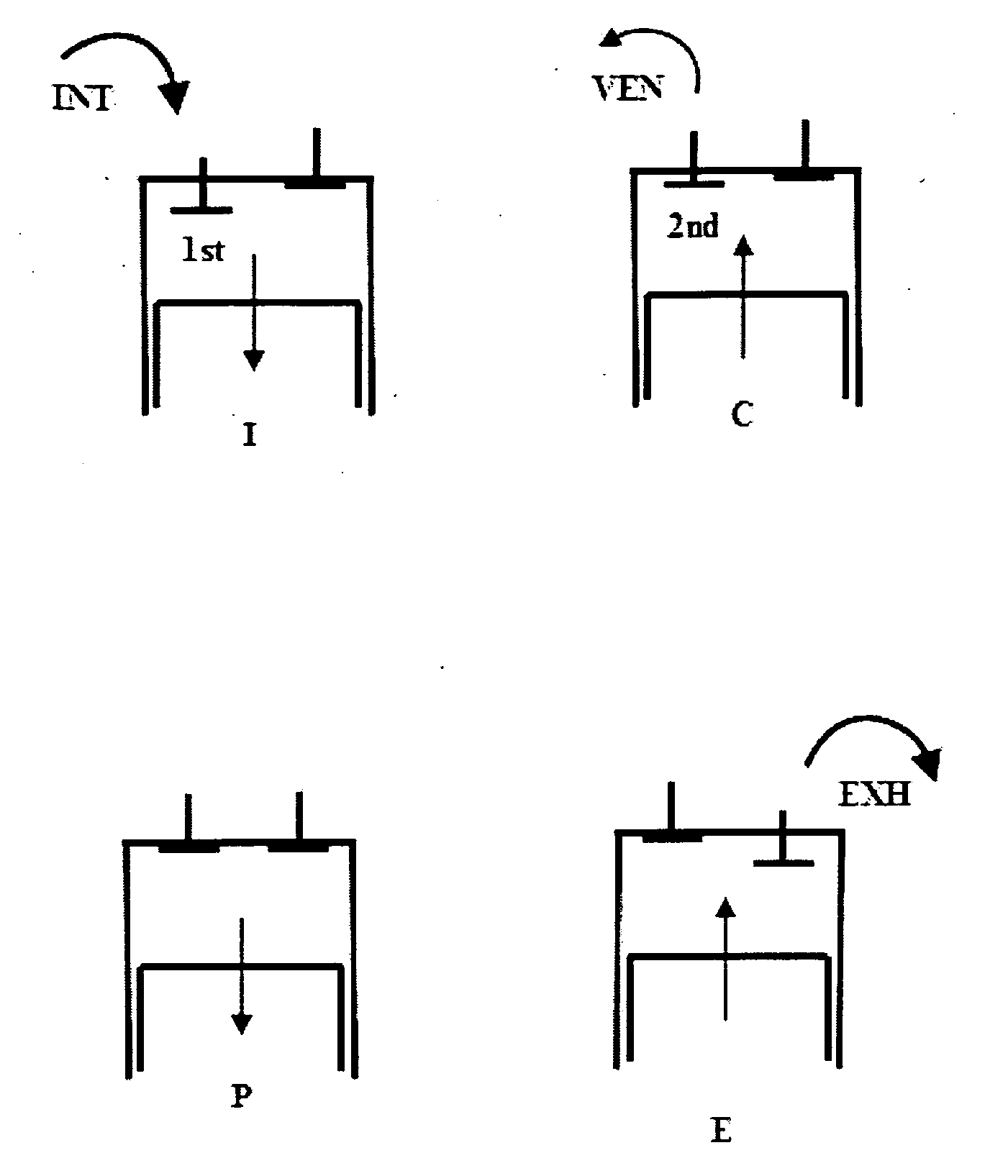
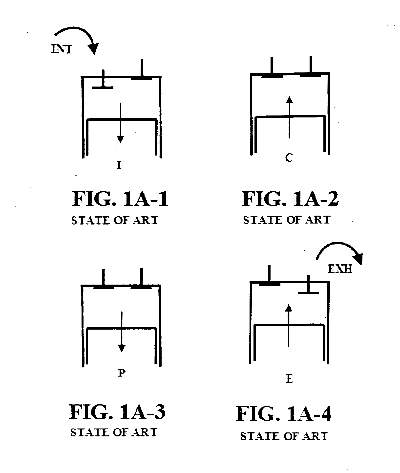
[0029]Attention is turned to FIGS. 1A-1-1A-4, which illustrate the state-of-art four strokes of an internal combustion engine. These, in the sequence of operation, are the Intake I in FIG. 1A-1, the Compression C in FIGS. 1A-2, the Power P in FIG. 1A-3 and the Exhaust E in FIG. 1A-4. The intake gas—charged into the cylinder—is labeled INT in FIG. 1A-1 and the exhaust gas—discharged from the cylinder—is labeled EXH in FIG. 1A-4. The intake valve opens once in the intake phase and the exhaust valve opens once in the exhaust phase normally, that is all along the intake and exhaust strokes correspondingly.

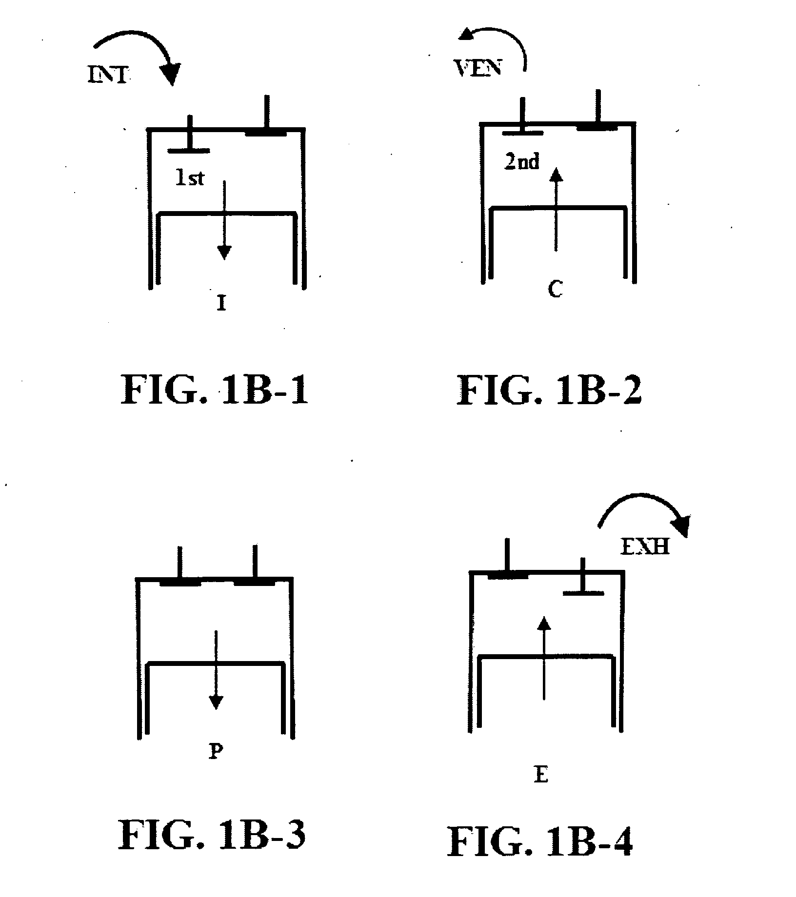
[0030]In the followings, this normal operation will be referenced as gas Cycle A of a diesel engine. All the proposed gas cycle modifications (B, C, D, E, F, I and J) will describe Diesel cycles thereof. However, all are applicable to Otto cycles as well, with the restriction of not to vent air-fuel-mixture into the exhaust manifold, and not to let it escape from the intake manifold, b...


PUM


Abstract

Disclosed is an internal combustion engine gas cycle modification process, comprising venting, which allows for some automatic gas transfer from intake to exhaust or vice versa, through the cylinder, in the compression or expansion strokes, by a second or third opening of either the intake or the exhaust valves, which is done by using a second or third auxiliary lobe on the intake or the exhaust cams, which however are much smaller than the normal lobes. Seven gas cycle modifications are explained and compared, each of which reduces NOx by 300-9,000× and cleans emission in the cylinder. On the same fuel consumption, all these modified gas cycles preserve torque and power. One however, increases high engine speed power and torque by over 70%. That may be exchanged for fuel savings. Double and triple lobe cams made the same way and cost the same as single lobe cams. It substitutes after-treatments.

Description

CROSS-REFERENCE TO RELATED APPLICATION[0001]This application claims the benefits of U.S. Provisional Patent Application Ser. Nos. 61 / 575,535 of Priority Date Aug. 24, 2011, and 61 / 575,318 of Aug. 19, 2011 and 61 / 574,803 of Aug. 11, 2011.FIELD OF THE INVENTION[0002]This invention relates to in-cylinder NOx reduction and emission cleaning with altered gas cycle for internal combustion engines. More specifically, to internally venting the cylinder gas in-compression and / or in-expansion to quench and / or dilute the combustion respectively and to boost the effective expansion-to-compression ratio for higher efficiency or fuel savings by valve timing alone, using modified cam profiles, which opens more than once in a complete gas cycle of intake, compression, expansion (power) and exhaust.BACKGROUND OF THE INVENTION[0003]Well known are the Otto (1867), Atkinson (1882), Diesel (1893) and Miller (1940) gas cycles, used in internal combustion engines today. Basic cycles are the Otto (spark ig...

Claims


Application Information

Patent Timeline
IPC IPC(8): F02B75/00F02B75/02
CPCF02B2275/32Y02T10/142F02D2041/001F02D2400/02F02D2400/04F02D13/0273F01L13/0015F02M25/0752F02D13/0211F02D13/0269F01L1/08F02M26/01Y02T10/12
Inventor KEMENY, ZOLTAN A.FEKETE, ALBERT
Owner KEMENY ZOLTAN A
Why Eureka
Try Eureka